Power, Grounding – GAI-Tronics 12576-504 Rack-Mount System Status panel with LCD Display User Manual
Page 4
Pub. 42004-436C
Model 12576-504 ADVANCE Rack-Mount System Status Panel with LCD Display
Page: 4 of 9
f:\standard ioms - current release\42004 instr. manuals\42004-436c.doc
01/12
Power
The modular terminal block labeled CLASS
2
12V
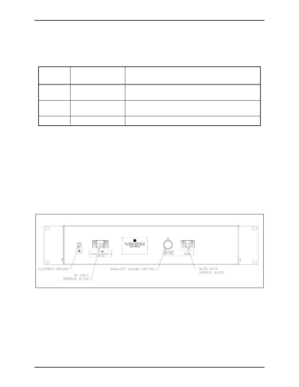
DC provides power connection for the system status
panel. Refer to Table 2 and Figure 3 for terminal details.
Table 2. DC Power Terminal Assignment
Label
Internal Terminal
Number
Function or ACT Description
+
TB2-1
Positive terminal of external power supply
(Red wire from 12 V dc power supply)
−
TB2-2
Negative terminal of external power supply
(Black wire from 12 V dc power supply)
GND
TB2-3
Frame/chassis ground
N
OTE
: The system status panel does not have an on/off power switch and will power up immediately
upon application of 12 V dc power. The ADVANCE System control cabinet must also be powered and
running before the system status panel is operational. The A
CK
/N
EXT
switch LED on the system status
panel will flash, the sonalert will sound and the display will read “No communication with ADVANCE”
until data communication is established with the ADVANCE control cabinet.
Grounding
The system status panel is equipped with a ground stud on the rear panel. The ground stud is supplied
with two KEPS type hex nuts. Internally, the ground stud connects to chassis and the ground terminal at
TB3-3. Be sure to connect this ground stud to the appropriate ground bar or ground terminals within the
cabinet using a #6 ring lug crimped to a No. 14 AWG green/yellow (or green) wire.
Figure 3. System Status Panel Rear View