Jumper settings, Tx/rx data, Potentiometer adjustments – GAI-Tronics 12576-504 Rack-Mount System Status panel with LCD Display User Manual
Page 6: Lcd display brightness, Lcd display contrast, Attaching the cover
Pub. 42004-436C
Model 12576-504 ADVANCE Rack-Mount System Status Panel with LCD Display
Page: 6 of 9
f:\standard ioms - current release\42004 instr. manuals\42004-436c.doc
01/12
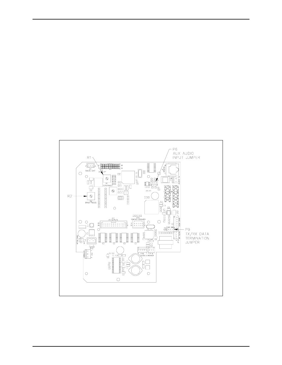
Jumper Settings
TX/RX Data
Jumper P9 provides a ground reference to the access panel data line. A similar jumper is located on the
Access Panel Interface (API) card in the system control cabinet. The data line must be ground referenced
on one side of the communication link but not both. Place P9 in the GND position to create a ground
reference. Place P9 in the FLOAT position (default) to remove the ground reference. Refer to Figure 5
for jumper location.
Potentiometer Adjustments
LCD Display Brightness
R2 adjust the brightness of the backlight of the display. Clockwise rotation increases the brightness.
Refer to Figure 5 for potentiometer location.
LCD Display Contrast
R1 adjusts the contrast of the display. Clockwise rotation increases the contrast. Refer to Figure 5 for
potentiometer location.
Figure 5. System Status Panel Board
Attaching the Cover
After all adjustments have been completed, replace the cover over lower chassis, being careful not to
pinch any cables. Secure the cover using the six screws originally removed from the top and sides.