Internal, Ring relay pcba – GAI-Tronics 352-101 Division 1 SMART Telephones User Manual
Page 7
Pub. 42004-455B
Model 352-101, 352-102, 352-103, & 352-104 Div. 1 SMART Hazardous Area Telephones Page 7 of 17
f:\standard ioms - current release\42004 instr. manuals\42004-455b.doc
02/13
Internal
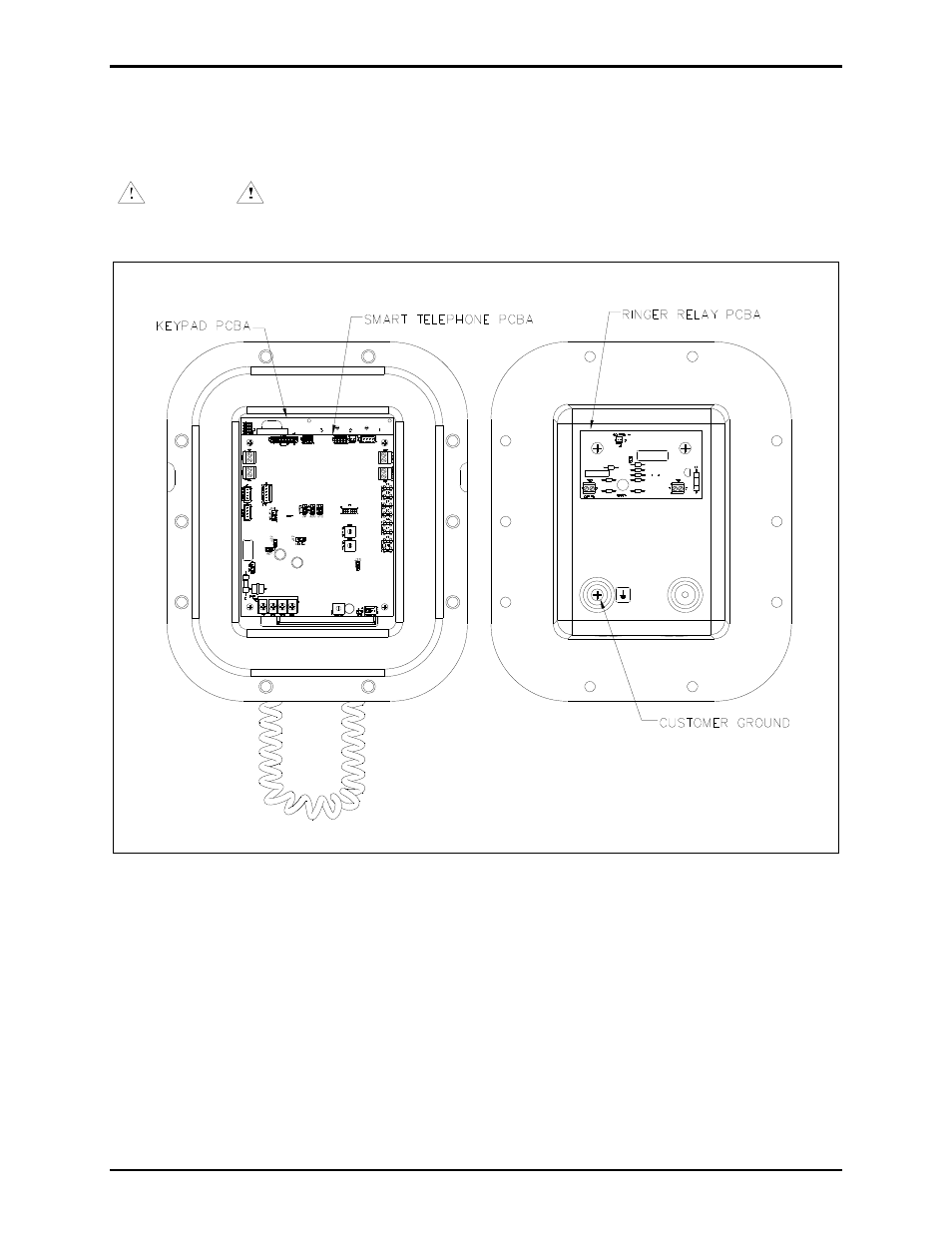
With the exception of the ring relay (when fitted), all standard components are mounted to the rear of the
front cover. See Figure 6 for the parts layout.
WARNING
The front cover is not hinged to the rear enclosure. When the flange bolts are
removed, the cover must be adequately supported.
Figure 6. 352 Series Division 1 SMART Hazardous Area Telephone - Internal View
Ring Relay PCBA
The Ring Relay PCBA allows the telephone to activate an external beacon or sounder when the telephone
receives a call. When installed, the Ring Relay PCBA is connected to the Main PCBA via a two-wire
cable assembly. This cable assembly allows communication between the Main PCBA and the Ring Relay
PCBA. The Ring Relay PCBA is located in the rear enclosure. See Figure 6 for mounting, and steps 3
through 5 in the “Wiring” section.