Wiring – GAI-Tronics 352-101 Division 1 SMART Telephones User Manual
Page 8
Advertising
Pub. 42004-455B
Model 352-101, 352-102, 352-103, & 352-104 Div. 1 SMART Hazardous Area Telephones Page 8 of 17
f:\standard ioms - current release\42004 instr. manuals\42004-455b.doc
02/13
Wiring
WARNING
The front cover is not hinged to the rear enclosure. When the cover bolts are
removed, the cover must be adequately supported.
1. While supporting the front cover, remove the ten cover bolts from the enclosure flange. Pull the front
cover far enough away to expose the internal connections and disconnect any wiring between the
front cover and rear enclosure. Place the front cover aside.
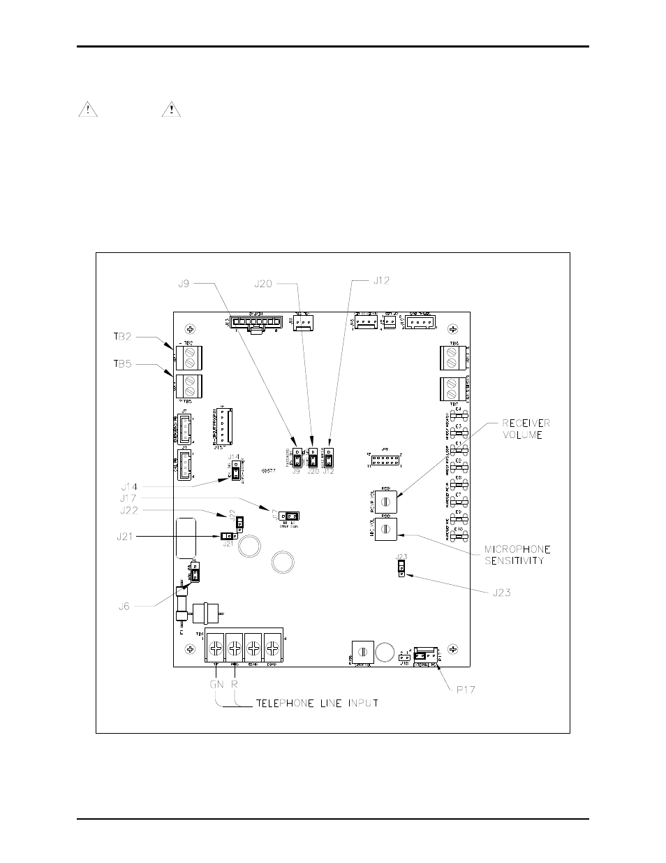
2. Connect the incoming subscriber line or the telephone line suppressor (if applicable) to TB1 on the
Main PCBA. See Figure 7.
Figure 7. Main PCBA
Advertising
This manual is related to the following products: