Outputs – GAI-Tronics 352-701 UL Class 1 Division 1 VoIP Telephones User Manual
Page 10
Pub. 42004-456C
Model 352-701 and 352-703 Division 1 VoIP Telephones
Page 10 of 20
f:\standard ioms - current release\42004 instr. manuals\42004-456c.doc
02/15
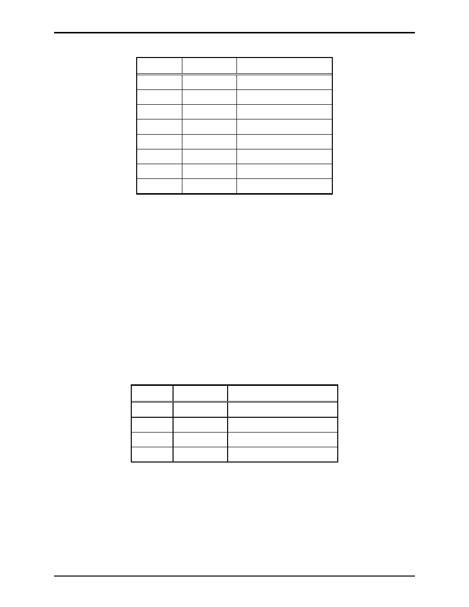
Table 1. Auxiliary Inputs – P12
Pin Label
Function
1 IN4
Input
4
2 COM Common
3 IN3
Input
3
4 COM Common
5 IN2
Input
2
6 COM Common
7 IN1
Input
1
8 COM Common
Outputs
Two outputs have been provided for customer use. Terminations for these outputs are provided on
connector P10.
Each VoIP Telephone contains two voltage-free output contacts. Refer to the “Specifications” section of
this manual for the output ratings. Both outputs are single-pole, single-throw contacts.
The function of each output is configurable. Outputs can be configured for one of the following modes:
On, Off, Pulse, Mute, Ring, Call, Connect, Hook, In Use, Ring Cadence, Ring Out, Page, Registered, or
Emergency. In some modes, the duration of the activation or on/off times can also be set. Refer to the
“Logic Settings” section of GAI-Tronics Pub. 42004-481, “VoIP Telephone Configuration Guide” for
more details.
An external beacon or sounder can be activated with output 1 on the VoIP PCBA. The output must be
configured to “Ring” mode to activate the external device.
Table 2. Output Contacts – P10
Pin Label
Description
1
C1
Common Output 1
2
NO1
Normally Open Output 1
3
C2
Common Output 2
4
NO2
Normally Open Output 2