Wiring – GAI-Tronics 352-701 UL Class 1 Division 1 VoIP Telephones User Manual
Page 8
Pub. 42004-456C
Model 352-701 and 352-703 Division 1 VoIP Telephones
Page 8 of 20
f:\standard ioms - current release\42004 instr. manuals\42004-456c.doc
02/15
Wiring
WARNING
The front cover is not hinged to the rear enclosure. When the cover bolts are
removed, the cover must be adequately supported.
1. While supporting the front cover, remove the ten cover bolts on the enclosure flange. Pull the front
cover far enough away to expose the internal connections. Place the front cover aside.
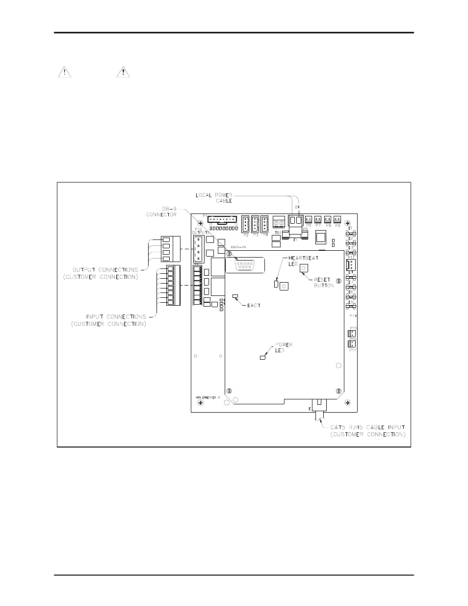
2. Plug the incoming Cat5 data line to the network Cat5 cable receptacle on the underside of the VoIP
PCBA. See Figure 7.
Install any additional connections as indicated below. Refer to Figure 7, 8 and 9 for wiring details. Refer
to Table 3 on page 11 for the recommended conductor sizes.
Figure 7. VoIP Telephone PCB Assembly