Mode 0: deactivate circuit – GAI-Tronics 379-002 Monitored RElay Module (MRM) Stations User Manual
Page 5
Pub. 42004-491A
Model 379-002 Monitored Relay Module Station
Page 5 of 13
f:\standard ioms - current release\42004 instr. manuals\42004-491a.doc
03/14
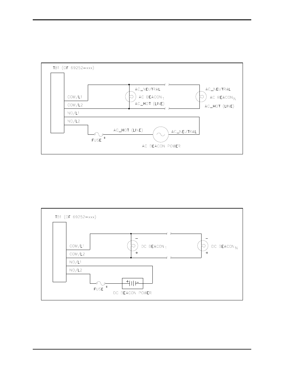
Mode 0: Deactivate Circuit
In Mode 0, outputs may be used to control several signaling devices by connecting/disconnecting power
to these devices. In this mode, no supervision of the loop is supported. This mode supports both ac- and
dc-powered signaling devices.
Figure 2. Deactivate Circuit - AC-Powered Beacons
Figure 2 shows the recommended wiring diagram for ac-powered signaling devices, while Figure 3 shows
the recommended wiring diagram for dc-powered signaling devices (using Output #1 as an example.)
*N
OTE
: The MRM does not contain any current-limiting for the signaling device power. It is
recommended that an external fuse be provided for each output circuit with the appropriate voltage and
current ratings. The selected fuse should be of the slow-blow variety.
Figure 3. Deactivate Circuit - DC-Powered Beacons