GAI-Tronics 703-005 Indoor RTU Enclosure User Manual
Page 4
Pub. 42004-617L2D
Model 703-005 SmartSeries
®
Indoor RTU Enclosure
Page
4 of 12
\\s_eng\gtcproddocs\standard ioms - current release\42004 instr. manuals\42004-617l2d.doc
10/03
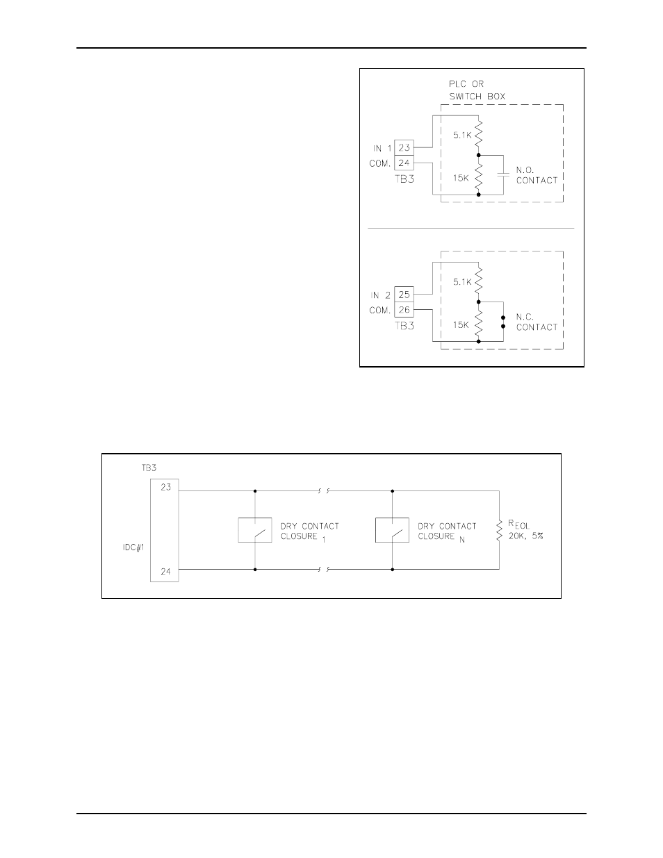
Configuration 2
The second configuration uses two supervised input
circuits and does not make use of the single relay
output. This configuration is accomplished by
interfacing to terminal block TB3-23 and TB3-24 for IN
1 and TB3-25 and TB3-26 for IN 2.
The external dry contact switch, either normally open or
normally closed respectively, should be in parallel to a
15 k-ohm resistor as shown in Figure 3.
A 5.1 k-ohm resistor should be in series to the 15
K-ohm resistor. This provides a voltage divider network
used to detect a short or open across the external
circuit’s cabling.
This configuration requires that the orange wire from
TB3-23 going to the relay output circuit be disconnected
so as not to interfere with supervised operation.
Another method of performing supervision using
multiple switches is shown in Figure 4. This method
requires only one 20 k-ohm resistor that is placed in
parallel to multiple normally open dry contact switches
at the end of line (EOL).
Figure 3. PLC or Switch Box
Normally Open and Normally Closed - Example
Figure 4. Input Line Supervision Multiple Switch - Example