Operation, Software configuration, Interface – GAI-Tronics 703-005 Indoor RTU Enclosure User Manual
Page 5
Pub. 42004-617L2D
Model 703-005 SmartSeries
®
Indoor RTU Enclosure
Page
5 of 12
\\s_eng\gtcproddocs\standard ioms - current release\42004 instr. manuals\42004-617l2d.doc
10/03
Configuration 3
In the third configuration, the relay output circuit is
non-supervised. This means the RTU can command a
system device to activate or deactivate without the
integrity of the external circuit being verified. In this
configuration, both inputs are available.
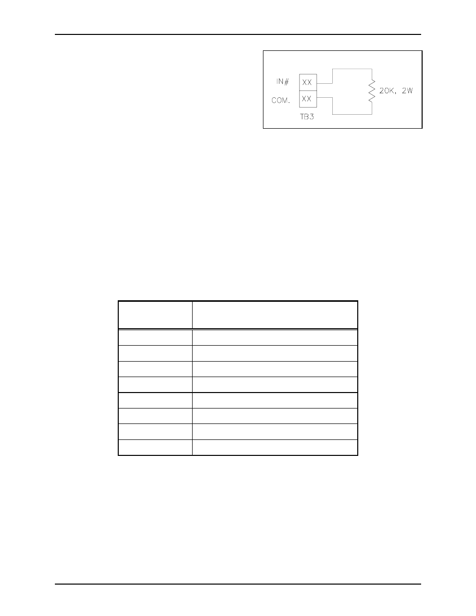
N
OTE
: Unused inputs must be terminated at terminal
block TB3 with a 20 k-ohm, 2-watt resistor. Resistors
are supplied with the units. See Figure 5.
Software Configuration
The software configuration of the RTU is accomplished through the use of the System Start-up Tool
(SST). The type of RTU is dependent on the hardware configuration. Before setting up the software, it is
important to know how the inputs and outputs will be used.
Interface
Use the ribbon connector supplied with the unit to connect the SmartSeries
®
relay circuit to the connector at
the base of the SmartSeries
®
station. Wiring to the RTU is performed by connecting the external circuits to
the appropriate lugs on the TB3 terminal block located on the rear panel on the enclosure. The following
table shows the wiring for TB3:
Terminal Block
Lug No.
Label
TB3-23 IN
1
TB3-24 Common
TB3-25 IN
2
TB3-26 Common
TB3-27 Spare
TB3-28
Black (hot) 120 V ac 50/60 Hz, 3 amps max.
TB3-29
White (neutral) 120 V ac 50/60 Hz
TB3-30 Earth
ground
The SmartSeries
®
RTU is pre-wired from the factory to support 1 supervised input and 1 supervised relay
output. To disable the supervision of the relay output circuit by IN 1, disconnect the orange wire going to
the relay circuit card located at TB3-23. This is the only wiring modification necessary for any of the three
RTU configurations.
Operation
The supervised input and relay output functions are supported by the ADVANCE system.
Figure 5. Unused Input