Power, Ac models, Dc models – GAI-Tronics DEX-101 Hazardous Area Driller's Intercom Station User Manual
Page 8
Pub. 42004-679L2G
M
ODEL
DEX-10
X AND
DEX-20
X
D
RILLER
’
S
I
NTERCOM
S
TATIONS
Page 7 of 13
f:\standard ioms - current release\42004 instr. manuals\42004-679l2g.doc
07/13
Power
A separate power feed is recommended for stations in Div. 1 areas so that the stations can be de-energized
for maintenance without disrupting the power supply to the other equipment in the Div. 1 area. Refer to
Figure 4 and Figure 5 for wiring details. Remove the termination enclosure cover and pull all wiring into
the termination enclosure. Terminal block TB2 is provided for connection of power to the station.
Terminate all conductor ends using #6-32 screws lugs.
AC Models
Terminate the 120-240 V ac 50/60 Hz feed on TB2. This terminal block can also be used to connect 120-
240 V ac 50/60 Hz to the next station. The maximum current of the ac feed shall not exceed 20 amperes.
Refer to Figure 5 for more details.
DC Models
Refer to Figure 4. Terminate the 24 V dc feed on TB2. This terminal block can also be used to connect
24 V dc to the next station. The maximum current of the dc feed shall not exceed 20 amperes. Power
must be supplied by an isolated 24 V dc power source. Additional power feeds may be required to
increase the system distance and/or the number of stations.
N
OTE
: Isolated dc power sources must be used for this installation. The 24 V dc source should be
located as close to the system center as possible.
Grounding the negative side of the power source at one point is recommended to ensure hum and noise-
free operation. Noise present on dc power lines can negatively affect station operation. Therefore, noise
should be limited to 10 mV or less.
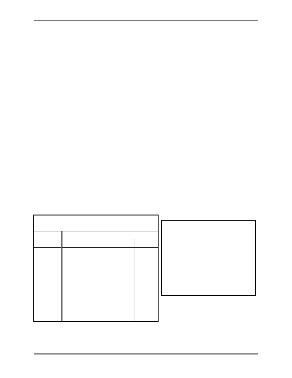
When installing this equipment, the power cable length is an important consideration. Refer to Table 1
for the recommended wire sizing details and the maximum cable lengths. This table is a guideline that is
useful in most applications; however, the installer must take into consideration any parameters specific to
their application.
Table 1. Maximum Distance between
Driller’s Intercom Stations (in feet)* (DC)
# of
AWG Wire
Stations
12
14
16
18
1
906 570 358 225
2
302 190 119 75
3
151 95 59 37
4
90 57 35
-------
5
60 38
-------
-------
6
43 27
-------
-------
7
32 ------- ------- -------
8
25 ------- ------- -------
*This chart is based on the following
parameters:
1. V(max) = 27 V
2. V(min) = 21 V
3. Cable temperature rating = 90 ºC
4. The American Wire Gauge
resistance table
For V(max) of 24 V, multiply the
distance shown by a factor of 0.47.