Auxiliary devices – GAI-Tronics DEX-101 Hazardous Area Driller's Intercom Station User Manual
Page 9
Pub. 42004-679L2G
M
ODEL
DEX-10
X AND
DEX-20
X
D
RILLER
’
S
I
NTERCOM
S
TATIONS
Page 8 of 13
f:\standard ioms - current release\42004 instr. manuals\42004-679l2g.doc
07/13
Auxiliary Devices
Terminal block TB1 is provided for connection of the speaker, system cable, footswitch, and beacon.
This terminal block accepts a #12–22 AWG wire. Refer to Table 2 for the recommended conductor sizes.
Conductor ends can be stripped and terminated with or without a wire ferrule.
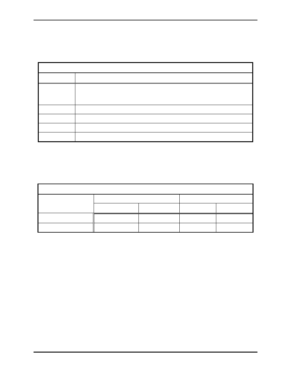
Table 2. Recommended Cable Sizes
Cable Use
Size
System
Digital: Two-conductor twisted pair, No. 22 AWG is typical
Analog: Four-conductor twisted pair (A/B twist; C/D twist), No. 22 AWG is
typical
Power
Three-conductor, No. 12 AWG is typical
Beacon
Two-conductor, No. 18 AWG is typical (for digital models only)
Footswitch
Two-conductor, No. 22 AWG is typical
Speaker Cable Two-conductor twisted pair, No. 18 AWG is typical
1. Install the system cable on TB1 system terminals A–D. Each system cable must be home run to the
Central. Digital stations require termination of a 2-conductor twisted pair cable on system terminals
A and B only. Analog stations require termination of a 4-conductor twisted pair cable (A/B twist &
C/D twist) on system terminals A–D. Refer to Table 3 for the maximum system cable lengths.
Table 3. Maximum System Cable Lengths
Digital Models
Analog Models
Cable Capacitance
No. 22 AWG
No. 20 AWG
No. 22 AWG No. 20 AWG
30.5 nf/1000 feet
6562 feet
6562 feet
4921 feet
6562 feet
13.7 nf/1000 feet
9843 feet
9843 feet
2. Install the speaker cable on TB1 Speaker terminals LS1 and LS2. Refer to Table 2 for recommended
conductor sizes.
3. Install the beacon control cable on TB1 terminals C1 and C2. This control output is available on
digital stations only. Refer to Table 2 for recommended conductor sizes.
4. Install the footswitch cable on TB1 terminals N.O. and C. Refer to Table 2 for recommended
conductor sizes.
After all connections are made, inspect and clean the machined and threaded surfaces of both the
termination cover and box. Clean the surfaces by wiping with a clean, lint-free cloth. Apply a light coat
of Killark LUBG lubricant to the cover threads. Install and hand-tighten the cover to the box.