Jumper settings, External audio input, Tx/rx data – GAI-Tronics 12576-501(x) ADVANCE Rack-Mount Access Panel with LCD Display User Manual
Page 9: Potentiometer adjustments, Lcd display brightness, Lcd display contrast
Pub. 42004-728L2D
Model 12576-501(x) ADVANCE Rack-Mount Access Panel with LCD Display
Page: 9 of 17
f:\standard ioms - current release\42004 instr. manuals\42004-728l2d.doc
08/12
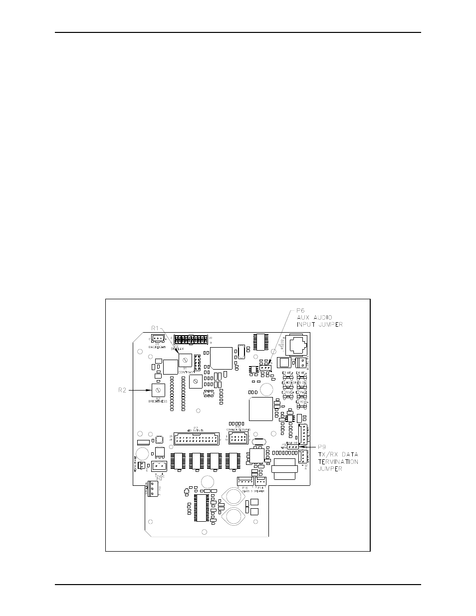
Jumper Settings
External Audio Input
Jumper P6 must be set to match the input level of the external audio source connected to the access panel
on TB2 (microphone level or line level). Place P6 in the HI position (default setting) for a line level
audio signal. Place P6 in the LO position for microphone level audio signals. Refer to Figure 9 for
jumper location.
TX/RX Data
Jumper P9 provides a ground reference to the access panel data line. A similar jumper is located on the
Access Panel Interface (API) card in the system control cabinet. The data line must be ground referenced
on one side of the communication link but not both. Place P9 in the GND position to create a ground
reference. Place P9 in the FLOAT position (default) to remove the ground reference. Refer to Figure 9
for jumper location.
Potentiometer Adjustments
LCD Display Brightness
R2 adjust the brightness of the backlight of the display. Clockwise rotation increases the brightness.
Refer to Figure 9 for potentiometer location.
LCD Display Contrast
R1 adjusts the contrast of the display. Clockwise rotation increases the contrast. Refer to Figure 9 for
potentiometer location.
Figure 9. Access Panel PCBA