GAI-Tronics 12522-003 Speaker Assembly Replacement Kit User Manual
Page 2
Page:
2 of 4
M
ODEL
12522-003
S
PEAKER
A
SSEMBLY
R
EPLACEMENT
K
IT
Pub. 42003-199B
\\s_eng\gtcproddocs\standard ioms - current release\42003 kit manuals\42003-199b.doc
01/04
2. If necessary, snip the tie wrap securing the following wires to each other: speaker, push button(s), LED
indicator, and in some cases, microphones.
3. Record the location of each connection to the PCBA (to aid in the connection of the replacement
PCBA) as you unplug all the connectors.
4. Remove the 4 screws holding the PCBA, and set the PCBA to the side.
Note: These models each have a shield that first must be removed.
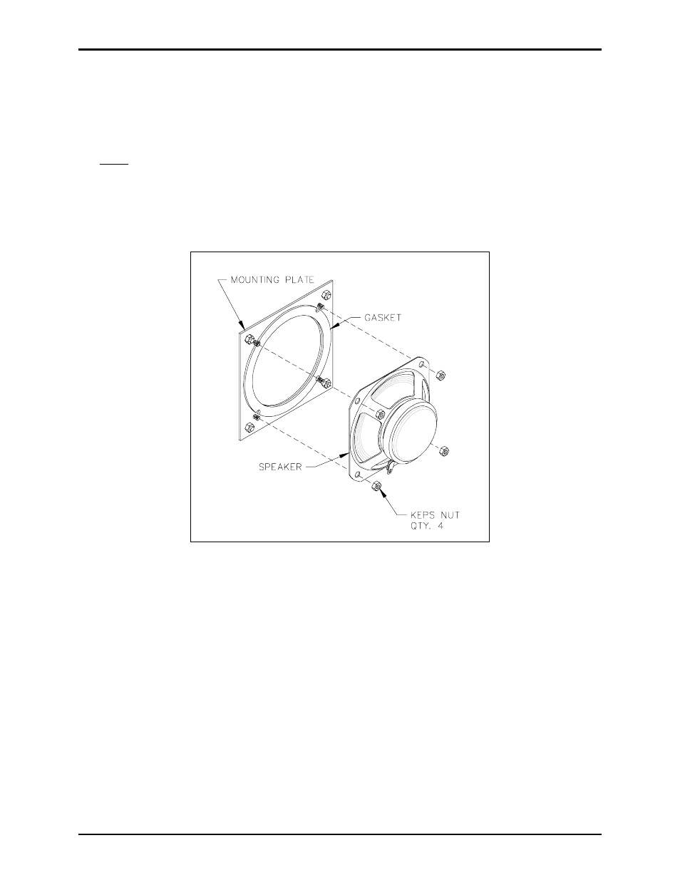
5. Remove the four 6-32 Keps nuts attaching the speaker to the speaker-mounting plate. Refer to Figure
1.
6. Remove the speaker and discard.
Figure 1. Models 297-xxx and 298-xxx
Installing the New Speaker Assembly
1. Attach the new speaker assembly with the original 6-32 Keps nuts, carefully applying equal pressure to
all four corners of the speakers.
2. Reattach the PCBA and shield using the original screws.
3. Plug in all of the connectors to the PCBA in their original locations.
4. Use the supplied tie wrap to secure the speaker assembly wire, as necessary.
5. Reattach the front cover.