Installation – GAI-Tronics 12522-003 Speaker Assembly Replacement Kit User Manual
Page 3
Page:
3 of 4
M
ODEL
12522-003
S
PEAKER
A
SSEMBLY
R
EPLACEMENT
K
IT
Pub. 42003-199B
\\s_eng\gtcproddocs\standard ioms - current release\42003 kit manuals\42003-199b.doc
01/04
Installation (
Models 293-00x, 293AL-00x, & 294AL-00x)
Removing the Old Speaker Assembly
CAUTION
Disconnect the phone line.
1. Use a Model 233 Tamper-resistant Screwdriver to remove the screws securing the front panel assembly
to the back box. Save these screws for re-assembly.
2. If necessary, snip the tie wrap securing the following wires to each other: speaker, push button(s), LED
indicator, and in some cases, microphones.
3. Record the location of each connection to the PCBA (to aid in the connection of the replacement
PCBA) as you unplug all the connectors.
4. Remove the 4 screws holding the PCBA, and set the PCBA to the side.
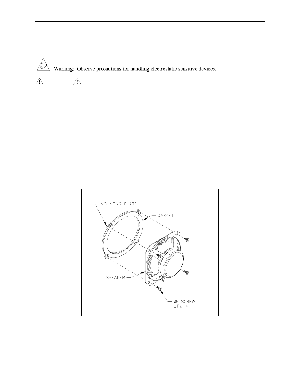
5. Remove the four #6 screws attaching the speaker to the speaker-mounting plate. Refer to Figure 2.
6. Remove the speaker and discard.
Figure 2. Models 293-xxx, 293AL-xxx, and 294AL-xxx