Greenheck 331-2976, 332-2976 - Siemens 4 Actuator (454202) User Manual
Installation instructions, Caution, Warning
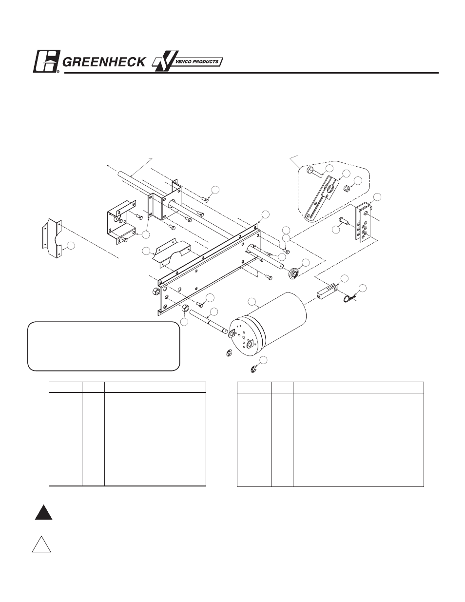
Part No. Qty.
Description
11
4
1
/
4
in.-20 Spinlock Nut
12
1
Mounting Bracket
13
1
Ball Bearing
14
1
Stand Off Bracket
15
4
#14 x
3
/
4
in.
Tek Screw
16
1
Auxiliary Bracket
17
4
#10 x
1
/
2
in. Tek Screw
18
1
3
/
8
in.-16 x 2
1
/
2
in. Carriage Bolt
19
1
3
/
8
in.-16 Spinlock Nut
These instructions apply to the external field installation of Siemens actuators on Greenheck model VCD Control Dampers when
they are duct mounted or sleeved.
These Siemens pneumatic actuators have an effective diaphragm area of 11 square inches and a 4 in. stroke. They all extend to
their holding position when air pressure is applied and spring return to their fail position when the air supply is interrupted. All
models have a maximum air pressure of 25 psi.
15
12
11
17
13
4
9
1
3
17
2
7
16
14
16
5
19
6
18
8
Damper Shaft
10
Parts for 1 in. Jackshaft
Tools Required:
Wrenches:
(1)
3
/
8
in., (2)
1
/
2
in., (1)
7
/
16
in.,
and (1)
3
/
4
in.
Part No. Qty.
Description
1
1
Actuator Siemens #4
2
2
1
/
2
in.-20 Hex Nut
3
1
Post
4
1
Clevis
5
1
Crankarm
1
/
2
in.
6
1
Crankarm 1 in.
7
2
1
/
2
in. E-ring
8
1
3
/
8
in. Clevis Pin
9
1
Cotter Pin
10
4
1
/
4
in.- 20 x
1
/
2
in. Bolt
InsTallaTIon InsTRucTIons
Part number 454202
siemens #4 actuator
Models 331-2976 & 331-2968
ul listed Pneumatic actuators with spring Return
!
!
cauTIon
Device Malfunction Hazard. Improper set screw tightening causes device malfunction. Tighten set screws with
proper torque to prevent damper shaft slippage.
!
!
WaRnInG
Equipment Damage or Electrical Power Hazard. Line voltage can cause death or serious injury and short equipment
circuitry. Disconnect power supply before installation.