Greenheck CRD-3XX and CRD-7XX Series for SP fans (452832) User Manual
Damper installation to a sp fan model
Document Number 452832
Installation Instructions CRD-3XXX, CRD-3XXL &
CRD-700 Series Dampers on Model SP Fans
These installation instructions show recommended
installation procedures. These or other installation
methods may be followed subject to the approval of
the authority having jurisdiction.
Model CRD-310, 320, 350, 360, 310L, 320L and
700 are specific sizes of Greenheck Model DFD-
350 dampers equipped with hardware to facilitate
installation with Greenheck Model SP ceiling exhaust
fans. The
CRD-3XX series and CRD-700 dampers are classified
by UL to function as a heat barrier in air handling
penetrations through fire resistive membrane ceilings.
They are intended to maintain the fire resistive
integrity of the ceiling. They can only be installed
in conjunction with the SP fan models shown and
cannot be installed alone.
Note: Motors for fan models used in conjunction
with CRD shall be equipped with thermal cut-off
fuse control.
UL CLASSIFIED (see complete marking on
product)
UL CLASSIFIED to Canadian safety standards (see
complete marking on product)
Standard UL555C
Classifications filed at UL under Listing #R13446
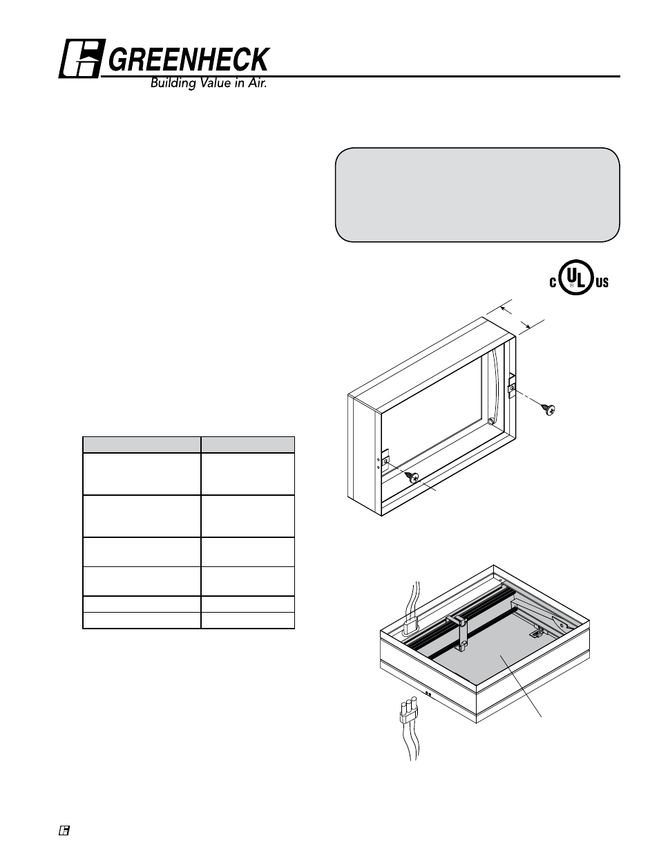
3.69”
Figure 1: Isometric view of a CRD-3XX series damper.
Figure 2: Isometric view for wiring the CRD-3XX series
damper to the lighted grille and ceiling fan.
Wires from lighted grille
Wires to ceiling fan
Do not allow
interference in
this area
SP Fan Size
CRD Model
SP-B50, SP-B70, SP-B80,
SP-B90, SP-B110,
SP-B150, SP-B200
CRD-320
CRD-320L
SP-A50, SP-A70, SP-A90,
SP-A110, SP-A125,
SP-A190
CRD-310
CRD-310L
SP-A250, SP-A290,
SP-A390, SP-A200
CRD-320
SP-A410, SP-A510,
SP-A710, SP-A780
CRD-350
SP-A900, SP-A1050
CRD-360
SP-A1550, SP-A700
CRD-700
Damper Installation to a SP fan model
Fan housing fits inside top flange of damper frame.
Observe label on damper indicating top.
Attach damper to fan housing using #10 x 3/4 in.
sheet metal screws on 6 in. maximum centers,
minimum two fasteners per side. See Figure 3.
Installation, Operation and Maintenance Instructions
®
®