Greenheck Concrete Floor with Steel Deck Supplement (463562) User Manual
Fd, dfd, & dfd-2xx series, Fsd, ssfsd, & cfsd series, Application
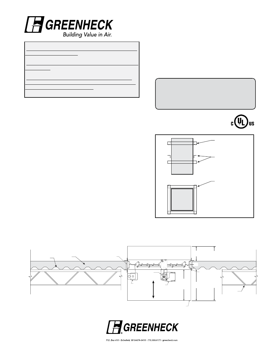
Application
Horizontal installation of FD, DFD, DFD-2XX, FSD,
SSFSD, and CFSD models in concrete floors utilizing a
steel deck. The hole opening made through the concrete
floor may not allow the bottom angle to be placed against
the steel deck on an even plane. This installation details
how to properly install the required retaining angles next
to the steel deck.
For single side retaining angle installations refer to
Greenheck document number 474015: Single Side
Retaining Angle Installation Instructions Supplement.
Notes for Two-Side Retaining Angle
Installations
1. Retaining angles are required on top and bottom sides of
damper as detailed in the Installation Instructions shown
above. Legs on angles may be reversed such that one leg
is inserted into the floor opening provided the required
clearance is maintained between angle leg fasteners and
the floor opening.
2. Installation of the bottom retaining angle against the
uneven steel deck shall be done such that the angles
on each side of the sleeve are as close to the barrier as
possible. In other words, the angles on each side of the
sleeve may be in different planes relative to each other
(see Figure 1 and 2).
3. When viewed from end of sleeve, the angles must overlap
each other in the corners such that no sight-through is
possible (see Figure 2).
Refer to:
‘Installation Instructions for FD, DFD, SSFD, SSDFD, & KFD
Series Curtain Fire Dampers’ (Part #452763)
or
‘Installation Instructions for FD and DFD 150X Series Curtain
Fire Dampers’ (Part #453946)
or
‘Installation, Operation and Maintenance Instructions for
FSD-XXX, SSFSD-XXX, DFD-2XX, & CFSD-XXX Series Fire
& Combination Fire Smoke Dampers’ (Part #461336) for
additional details.
Figure 1: Damper installed in concrete floor with steel deck.
Copyright© 2012 Greenheck Fan Corporation
463562 Concrete Floor with Steel Deck Supplement
Rev 4 August 2012
Concrete Floor
Clearance for expansion
(
1
⁄
4
in. min, 1
1
⁄
2
in. max.)
Airflo
w
Optional blade
indicator
and/o
r
electric link.
Access door required on
jackshaft side of damper.
Refer to the latest edition
of NFPA 90A.
Jackshaft
Actuator
16 in.
max.
6 in.
max.
C L
Damper
Sleeve
Retaining angles:
Place as close to
barrier as possible.
Angles on each side
of sleeve may be in
different planes.
Sleeve
Length (L)
‘A’ Dim.
(Distance from
end of sleeve to
face of damper)
LINE OF WALL
DO NOT INSTALL SCREW
S
BETWEEN THESE LINES
AROUND ENTIRE DAMPER
458549
Steel
Joists
Steel Deck
“UL CLASSIFIED (see complete marking on
product)”
“UL CLASSIFIED to Canadian safety standards
(see complete marking on product)”
Standard 555 (Listing #R13317)
Standard 555S (Listing #R13317)
Bottom angles
may be in
different planes
Angles must
overlap in
corners
End view
of sleeve
Side view
of sleeve
Top angle
Figure 2: Retaining angle installation.
Document Number 463562
Installation Instruction Supplement for
FD, DFD, & DFD-2XX Series
Fire Dampers and
FSD, SSFSD, & CFSD Series
Combination Fire Smoke Dampers
Installed in Concrete Floor with Steel Deck
®