Control module – Hypertherm PHC Sensor User Manual
Page 15
Section 1: Overview
15
Control Module
Electrical
Input power (switch selected dual range)................................ 115 VAC or 230 VAC, 1 Phase, 50/60 Hz
Parallel digital I/O ................................................................... + 12 Vdc
Motor drive output voltage ……………………….....................24 Vdc
Motor drive output current ……………………….....................2,3,4,6 Amps max DIP switch selectable
Motor brake output ………………………………......................+24 Vdc ½ Amp
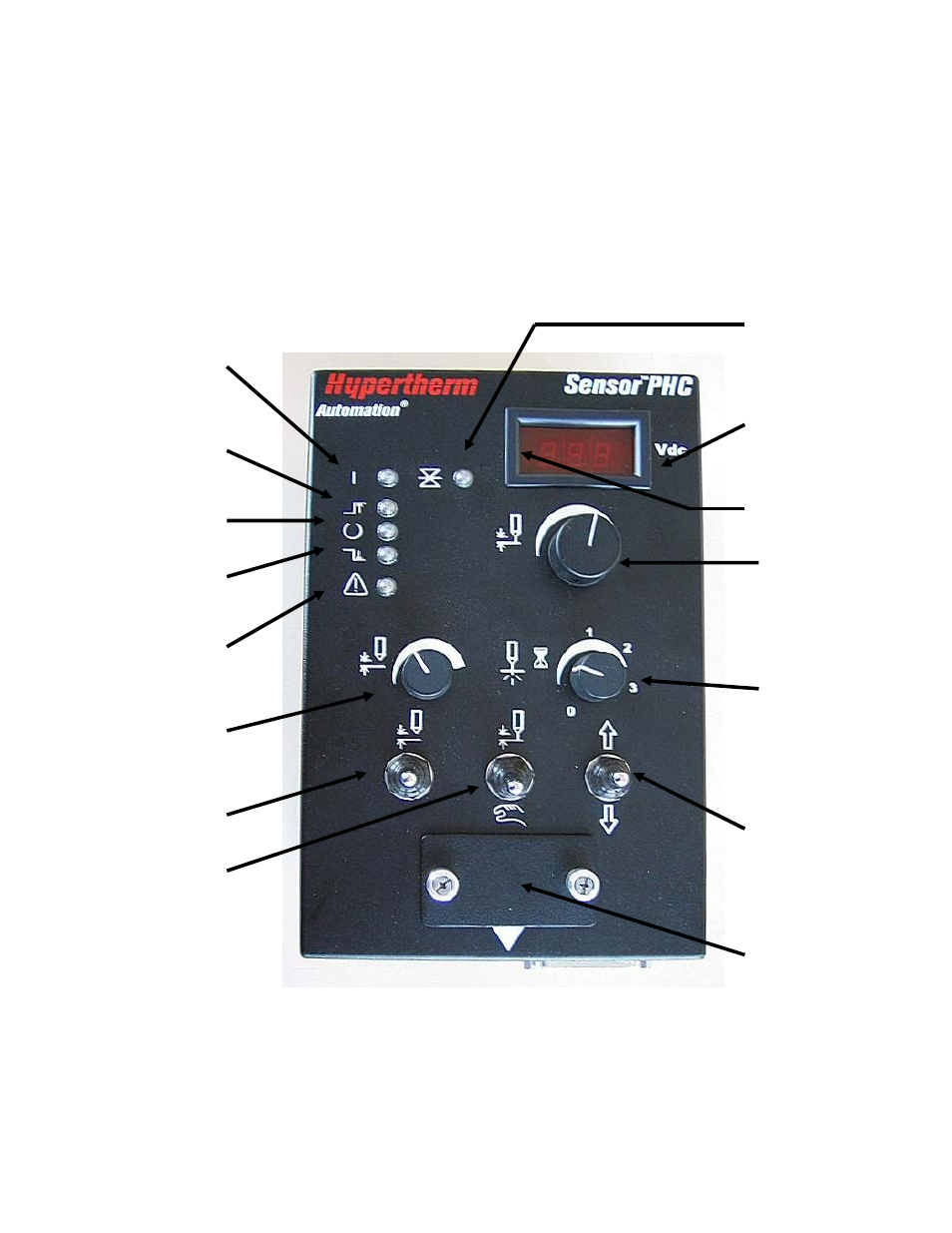
The features of the control module are highlighted in Figure 2.
Figure 2: Control Module
Calibration
and setup
Display actual /
set arc voltage &
errors
Set arc voltage
Set pierce
delay time
Manual up / down
for torch
Manual / auto
IHS test
Set IHS
height
Error
Lower limit
Voltage in
control
Upper limit
Power
Torch position hold
Plate contact LED