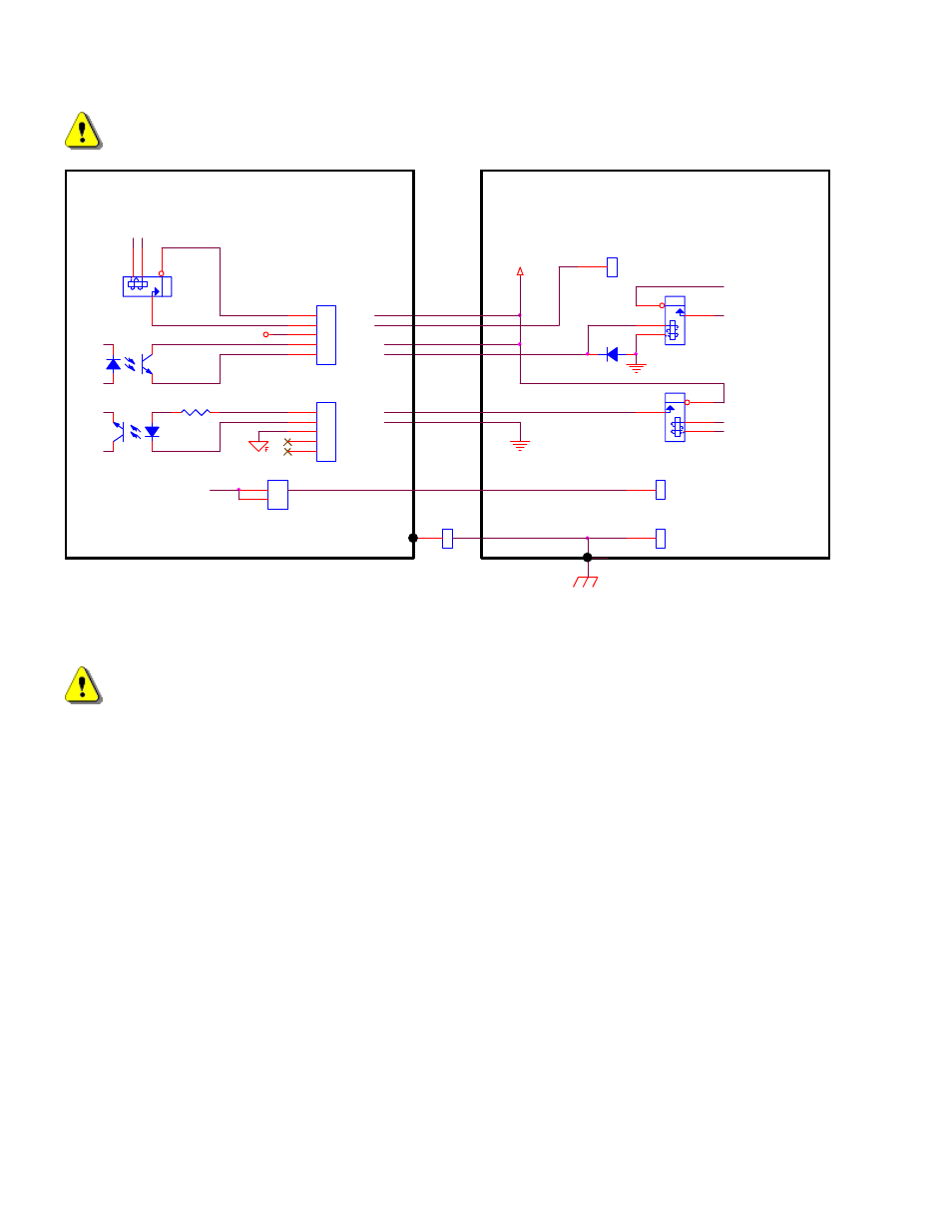
External plasma supply (using external +24v), Sensor phc plasma interface i/o, Figure 18: plasma interface connections – Hypertherm PHC Sensor User Manual
Page 36
36
Sensor™ PHC Operation and Setup Guide
WARNING! For safety and proper operation this unit must be connected to positive ground.
Work
Positive Ground
Electrode (Neg)
GND_External
+12V Field
PLASMA START (+24V)
HOLD
IGNITION
TRANSFER
J1
1
2
3
4
5
HLD-
J3
1
2
3
4
5
HLD+
XFR-
RELAY
OPTO
OPTO
3300
External Plasma Supply
(using External +24V)
STR
STR
XFR+
+24V External
GND_External
RELAY 24V coil
RELAY
DIODE
1
2
Electrode (Neg)
Sensor PHC Plasma
Interface I/O
Figure 18: Plasma Interface Connections
WARNING:
Observe signal polarities when connecting to optocouplers. Do not exceed 24Vdc on any signal lines. Do not
exceed 30mA current from any input or output. Do not exceed 50mA total current drawn from Sensor™
internal +12V field supply. Failure to observe these warnings could damage the unit.