Plasma interface assembly – Hypertherm PHC Sensor User Manual
Page 16
16
Sensor™ PHC Operation and Setup Guide
Plasma Interface Assembly
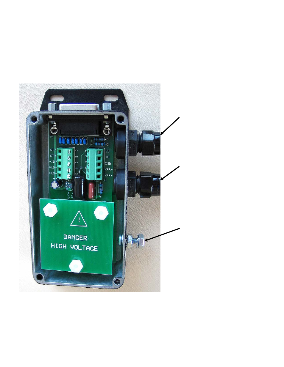
The plasma interface module is shown in Figure 3.
Electrical
Parallel digital I/O.....................................................................+12 Vdc to +24 Vdc
Interface signals……………………………………................... Plasma start, hold ignition, transfer
Voltage divider function............................................................Arc voltage (attenuated and filtered)
Figure 3: Plasma Interface (Cover Removed)
If you are using a Sensor PHC 228245 with an HSD 130, select plasma interface assembly 228247 (25-foot
cable) or 228248 (50-foot cable). Refer to Field Service Bulletin 805740 for installation information.
Plasma interface
signals
Electrode voltage
(negative)
Connection for ground
to the star ground on
the work table