Hypertherm HD3070 w/ Automatic Gas User Manual
Page 24
1-21
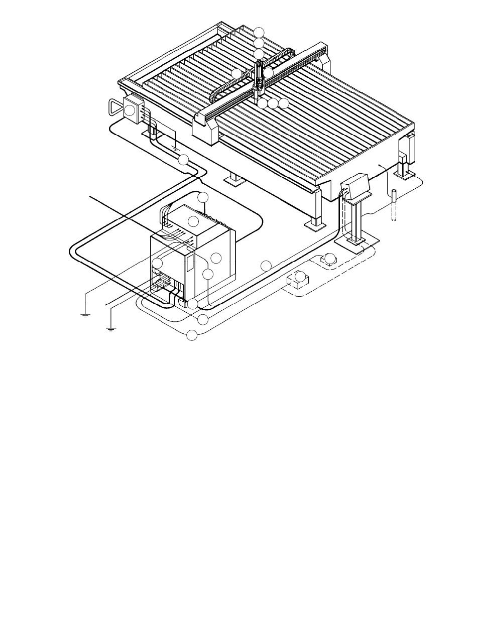
HD3070 w/Automatic Gas Console
1
2
3
6
7
8
9
13
14
17
16
15
17
19
18
24
23
21
20
4
5
1
HD3070 Power Supply, Auto
2
HD3070 Automatic Gas Console
3
Remote High Frequency (RHF) Console
4
Leads Between Power Supply and RHF Console
5
Work Cable Between Power Supply and Work Table
6
Leads Between Power Supply and Auto Gas Console
7
PAC186 Torch
8
Quick Disconnect Assembly - Straight
9
10 Inch Torch Mounting Sleeve
10
PAC184 Torch (not shown)
11
Quick Disconnect Assembly - 45
°
(not shown)
12
8 Inch Torch Mounting Sleeve (not shown)
13a Shielded Leads Between RHF Console and Torch (with Blow Down Check Valve & Hose)
13b Shielded Leads Between RHF Console and Torch (without Blow Down Check Valve & Hose)
14a Off-Valve Assembly (with Blow Down Solenoid Valve)
14b Off-Valve Assembly (without Blow Down Solenoid Valve)
15
48 Inch Shield Gas Hose Between Off-Valve Assy and Torch
16
48 Inch Plasma Gas Hose Between Off-Valve Assy and Torch
17
Leads Between Gas Console and Off-Valve Assy
18
Cable Between Gas Console and Cutting Machine Interface
19
Control Cable Between Power Supply and Cutting Machine Interface
20
Current Setpoint Cable Between Power Supply and Cutting Machine Interface or
Between Power Supply and RCC
21
Timer-Counter Cable Between Power Supply and Cutting Machine Interface or
Between Power Supply and Timer-Counter
22
Remote Current Control (RCC)
23
Timer-Counter
Figure 1-11 HD3070 w/Automatic Gas Console System Interconnect Example - 3D View
1-00