Layout of cutting machine and hd-3070 system – Hypertherm HD3070 w/ Automatic Gas User Manual
Page 7
1-4
HD3070 w/Automatic Gas Console
LAYOUT OF CUTTING MACHINE AND HD-3070 SYSTEM
When configuring an HD3070 system(s), it is important to know where each major compo-
nent will be placed. This will vary with the cutting machine manufacturer and with the particu-
lar installation. After the location of the major components has been determined, the inter-
connecting leads and cable lengths can be specified.
It is critical to follow the path that the interconnecting leads will follow and allow for some
slack when specifying their lengths. Do not try to get by with the next shorter length!
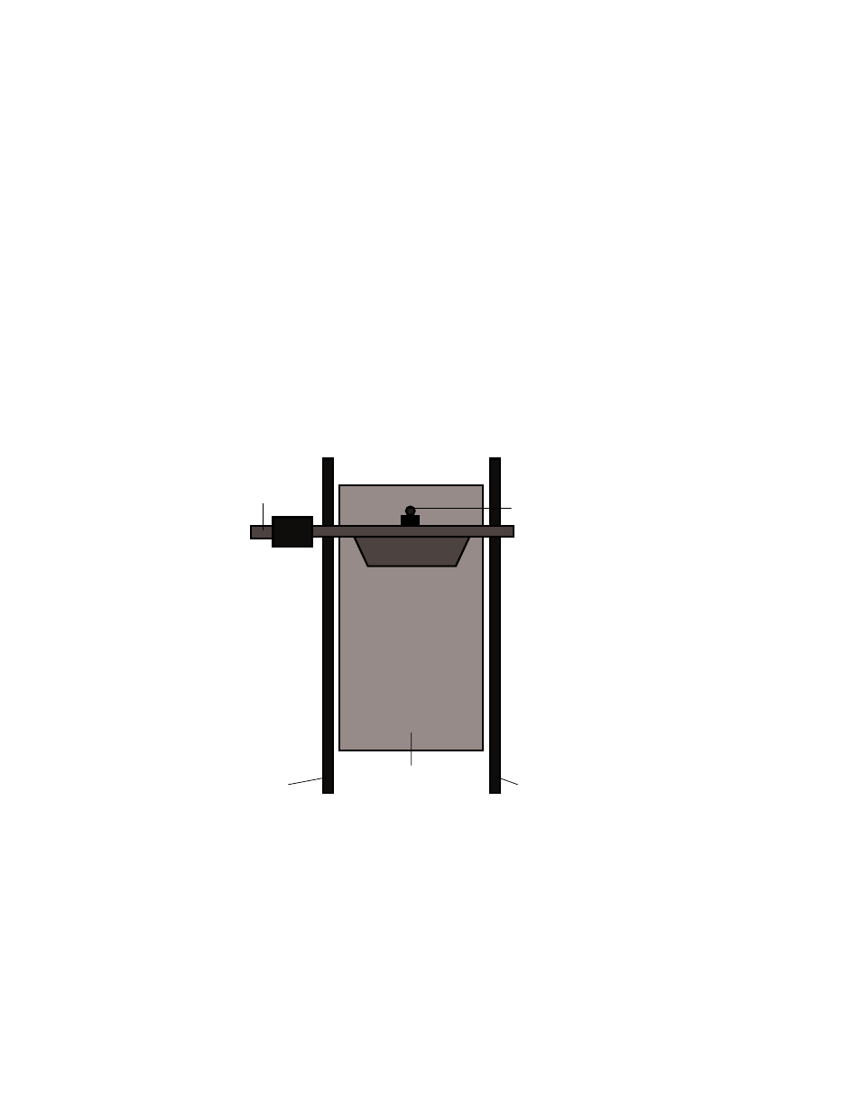
Pictured below is a diagram showing an overhead view of a typical precision cutting X-Y
machine. Installations vary, so use this figure as a guide.
Rail
Water
Table
Torch
Rail
Bridge
* Cables are usually in a power track or
festoon system. Cable, lead and hose lengths
must allow for routing through the system.
Figure 1-1 Gantry (Bridge) Layout)*