Quick reference to cable / hose dimensions – Hypertherm HySpeed HT2000 Plasma Arc Cutting System Rev.7 User Manual
Page 18
SPECIFICATIONS
HySpeed HT2000
Product Configuration Manual
1-13
6
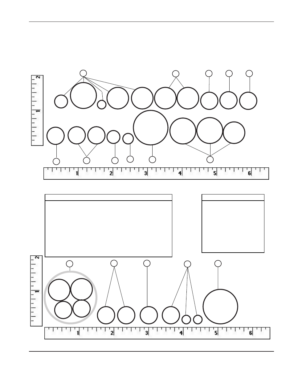
Quick Reference to Cable / Hose Dimensions
The following figures are a one-to-one representation of the HT2000 system interconnecting cables and hoses.
Figure 1-8 shows cables and hoses that would lay in the rail at the site. Figure 1-9 shows cables and hoses that
would lay in the cutting machine's cable/hose carrier. The rulers have been added to use as a guide. Arrangement
of cables and hoses laying in rails or carriers are roughly suggested here.
Figure 1-9
Cables / Hoses in Machine Cable/Hose Carrier
1/4"
3/8"
5/8"
5/8"
5/8"
5/8"
3/4""
1/2"
1/2"
1/2"
1/2"
1/2"
1/2"
3/8"
Figure 1-8
Cables / Hoses in Rail
1-1/2"
1/2"
1/2"
1/2"
1/2"
1/4"
1/4"
1"
3/4"
3/4"
5/8"
1"
5/16"
4
9
10
11
13
14
5
8
11
19
22
15
19
20
a
21
23
Key – Figure 1-8
Key – Figure 1-9
5
Shld Leads – Trch/RHF Csl
8
Leads – Gas Csl/
Mtr Vlv Csl
1/2" Preflow Hose
1/2" Cutflow Hose
11 Cable – Mtr Vlv Csl/PS
19
Ind. IHS Lead Set
1/2" IHS Air Cyl. Hose
1/4" IHS Snsr Probe Cbl (2)
21 WM System
1" W/M Pump to W/M Hose
15
Cable – PS/Mach. Comp.
1/2" Mach. I/O Cbl
1/2" Mach. V/C Cbl
19
Ind. IHS Lead
3/8" IHS Cntrl Cbl
20a Cable – Tmr-Cntr/PS
21
WM System
1" WM Pump/WM Hose
23
Hose – Supply/Gas Csl
3/4" Oxygen Hose
3/4" Shield Hose
5/8" Nitrogen Hose
4
Leads – PS/RHF Csl
3/8" RHF Csl Cntrl Cbl
3/4" Negative Cbl
1/4" Pilot Arc Cbl
5/8" Cooling Hose (2)
9
Shield Gas Hose – Gas Csl/
RHF Csl (2)
10
Cable – Gas Csl/PS
11
Cable – Mtr Vlv Csl/PS
13
Cable – PS 1X7/DR,PR, CR
14
Cable – PS 1X8/PR