Layout of cutting machine and ht2000 system – Hypertherm HySpeed HT2000 Plasma Arc Cutting System Rev.7 User Manual
Page 23
ORDERING PROCEDURE
2-4
HySpeed HT2000
Product Configuration Manual
6
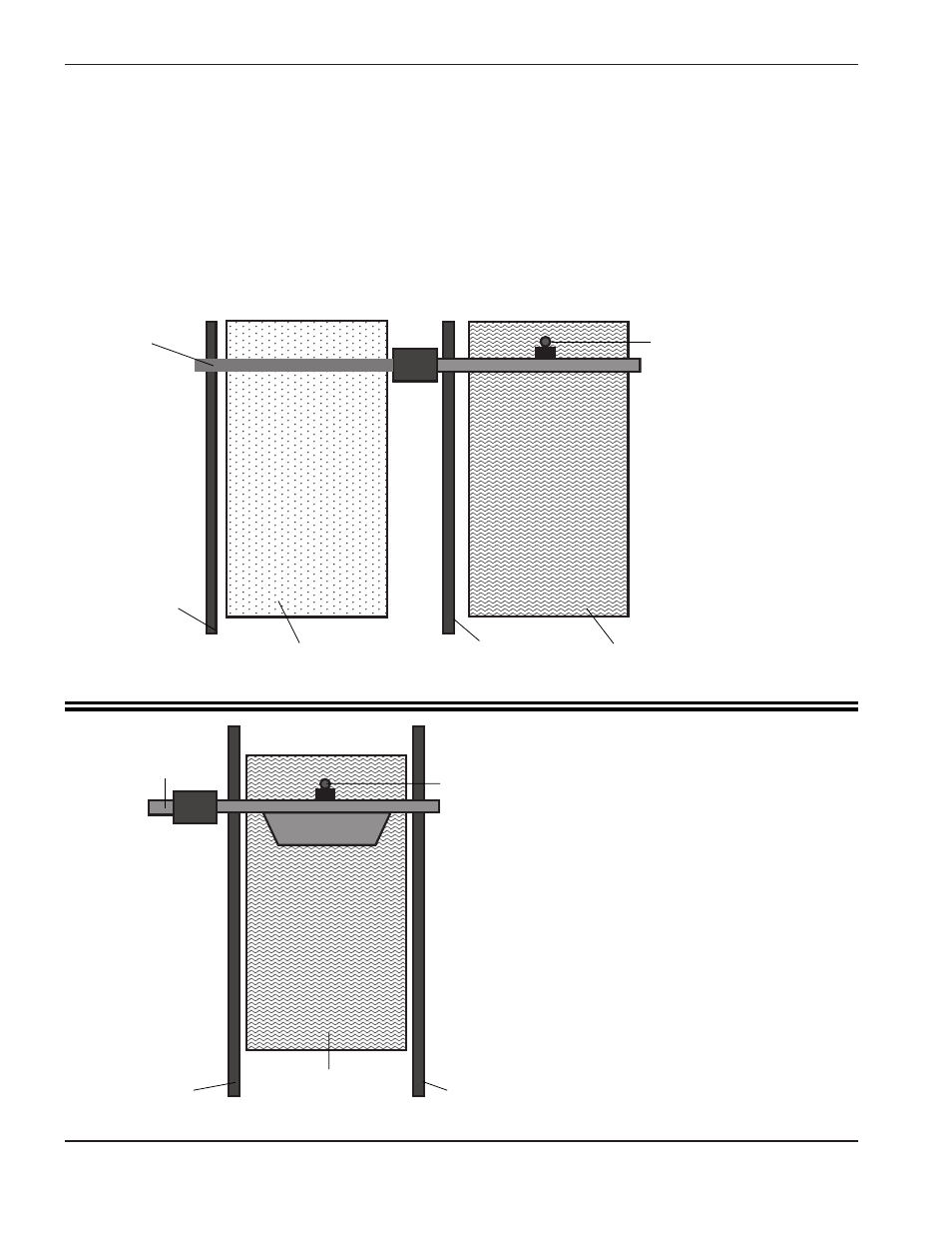
Layout of Cutting Machine and HT2000 System
When configuring an HT2000 system(s), it is important to know where each major component will be placed. This
will vary with the cutting machine type (gantry or cantilever) and with the particular installation. After the location of
the major components has been determined, the interconnecting leads and cable lengths can be specified.
It is critical to follow the path that the interconnecting leads will follow and allow for some slack when specifying
their lengths. Do not try to get by with the next shorter length! Cable stretchers are not provided.
Pictured below are two diagrams showing overhead views of typical cantilever and gantry systems. Installations
vary, so use these diagrams as a guide.
Rail
Water Table
Torch
Rail
Bridge
* Cables are usually in a power track or festoon
system. Cable, lead and hose lengths must allow
for routing through the system.
Figure 2-1
Gantry (Bridge) Layout*
Figure 2-1
Cantilever Layout*
Tracing Table
Rail
Rail
Cantilever
Water Table
Torch