IBASE MB945 User Manual
Page 28
Advertising
INSTALLATIONS
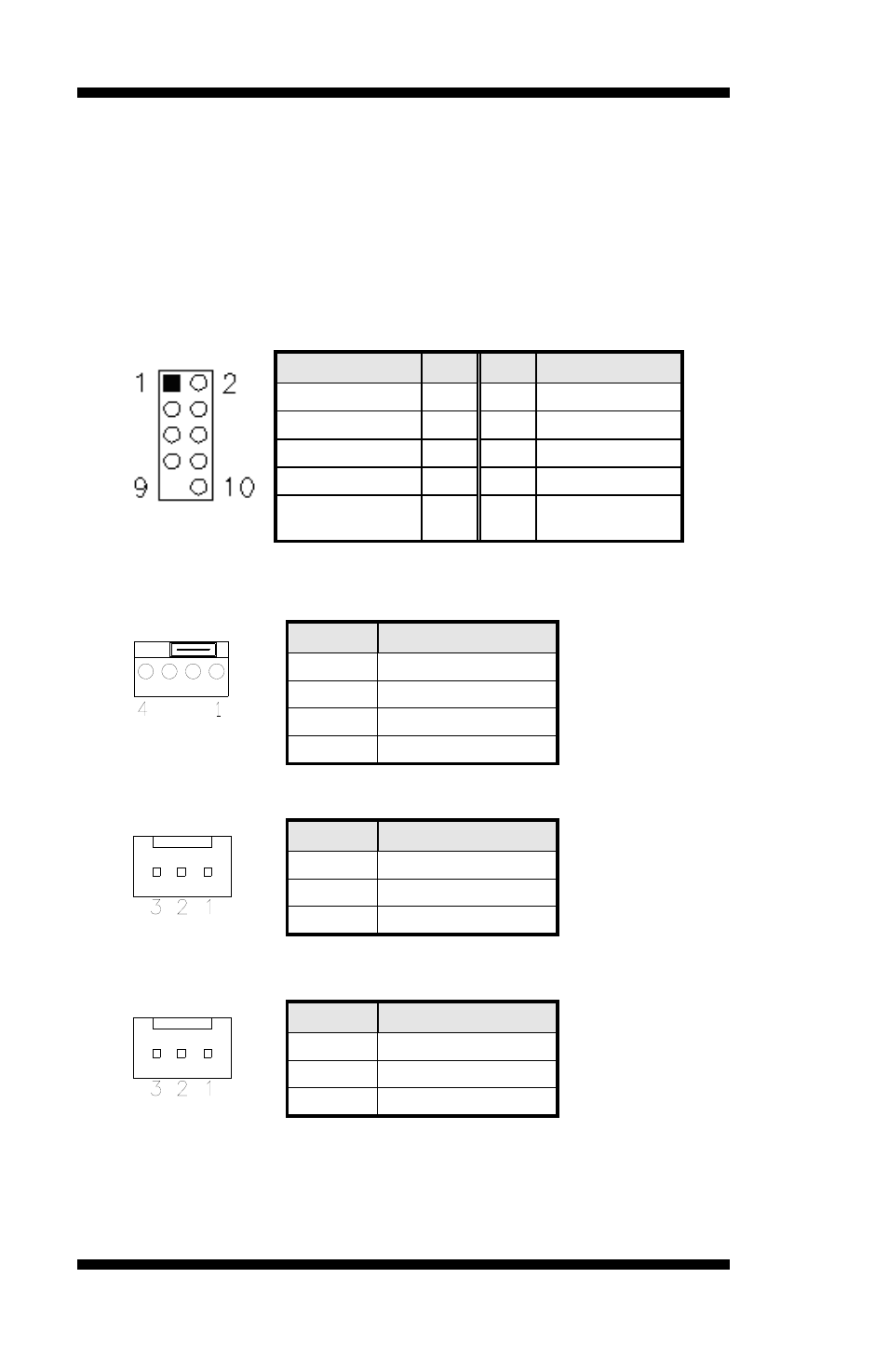
F_USB1: USB8/USB9 Connector
F_USB2: USB6/USB7 Connector
F_USB3: USB2/USB3 Connector
F_USB4: USB0/USB1 Connector
The following table shows the pin outs of the USB pin header.
Signal Name
Pin
Pin Signal Name
+5V 1
2 +5V
USBD0- 3
4 USBD1-
USBD0+ 5 6 USBD1+
Ground 7
8 Ground
Key pin
9
10
NC
CPU_FAN1: CPU Fan Power Connector
Pin #
Signal Name
1 Ground
2 +12V
3 Rotation
detection
4
Control
SYS_FAN1: system Fan1 Power Connector
Pin #
Signal Name
1 Ground
2 +12V
3 Rotation
detection
SYS_FAN3: SYSTEM Fan2 Power Connector
Pin #
Signal Name
1 Ground
2 +12V
3 Rotation
detection
24
MB945 User’s Manual
Advertising