Infloor Infloorboard II User Manual
Page 2
2
Introduction
Outstanding for both new construction and ret-
rofit, InfloorBoard II™ allows for the fast and
effective installation of PEX tubing in virtually
every application. No longer does one have to
deal with expensive or impractical lightweight
concrete pours or time consuming between floor
joist installations.
•
Unique single board design secures 3/8” PEX
tubing @ 8” on center spacing in any direc-
tion; straight, turns, or both.
•
24” x 24” dimensions allows for straightfor-
ward material calculations (sq.ft./4).
•
Adds only 5/8” to existing/planned floor height.
•
Open channel design leaves tubing fully visi-
ble and accessible during installation.
•
Tongue and groove edges allows for quick
interlocking installation and maximum surface
continuity.
•
Pre-drilled countersunk mounting holes pro-
vide for ease of installation.
•
Moisture resistant MDF construction offers
protection against high levels of humidity and
occasional wetting of the installation area
(basements, baths, kitchens,…)
•
Lightweight — 5 times lighter than concrete.
RADIANT DESIGN: The following steps are
provided as a guide in designing a radiant
floor heating system. Please consult with
your PEX tubing manufacturer for specific
design criteria.
Determining Your Heating Requirements
The room or area heating requirements must be
determined using a radiant design calculation or
adjusted conventional heat loss calculation.
System suppliers, local product representatives,
and wholesale distributors can all assist you in
determining your heating requirements.
Required Heat Output
The heat loss of any given area must be re-
placed with the heat output provided by the ra-
diant source (floor). It is important that only
“open” floor area (Net Area) be utilized in deter-
mining the Required Heat Output. The Net Area
is established by subtracting from the total
square footage all cabinets, fixtures and other
non heat producing areas.
Heat
Loss
Required Heat Output = —————-
Net
Area
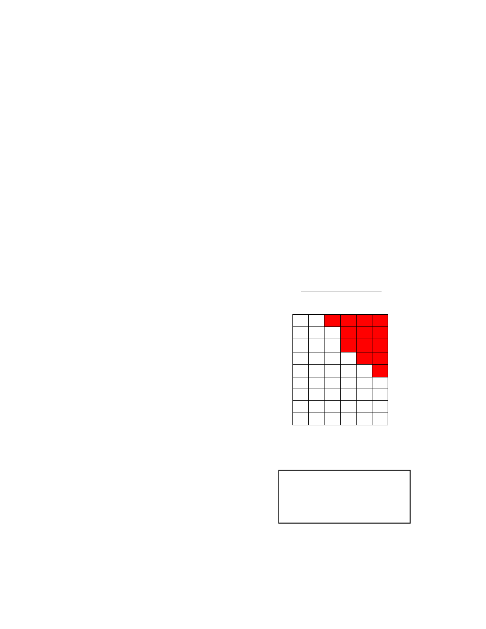
Supply Water & Surface Temperature
Using the Floor Output Chart the system Supply
Water Temperature and Surface Temperature
can be determined.
1.
Find the Required Output on the left side of
the chart and read across to the right to de-
termine the Surface Temperature.
2.
Calculate the Total R-Value of the floor cov-
ering material and extend a line up from this
point to where it intersects the Required
Output. The Supply Water Temperature can
be read at the point of intersection.
3.
If the Water Temperature is above 150˚F.
or the Surface Temperature is above 85˚F.;
a. Check the heat loss for accuracy. Has
it been determined for radiant heat?
b. Choose a floor covering with a lower R-
Value.
c. Reduce the heat loss of the area
(I.E. increased insulation, new windows)
d. Include supplemental heating for the
area.
45 145 159
90
40 138 150 168
87
35 130 142 157
85
30 123 132 144 159
83
25 114 122 133 145 160
81
20 107 113 122 131 143 165 78
15 102 106 111 118 128 143 76
10 93 97 100 104 112 123 73
5 87 89 91 93 97 102 70
0.5 1.0 1.5 2.0 2.5 3.0
Required Avg. Water Temp.
R-Value of
Floor Covering
Req.
Output
Btu/Sq.Ft.
Surface
Temp
(˚F.)
*Outputs provided for 3/8” PEX
Tubing at InfloorBoard II™ pro-
vided 8” on center spacing with
a 20˚F. delta T. operating at
steady state performance.
Floor Output Chart