K-Patents PR-03 User Manual
Page 36
36
36
36
36
30
PR-03 instruction manual
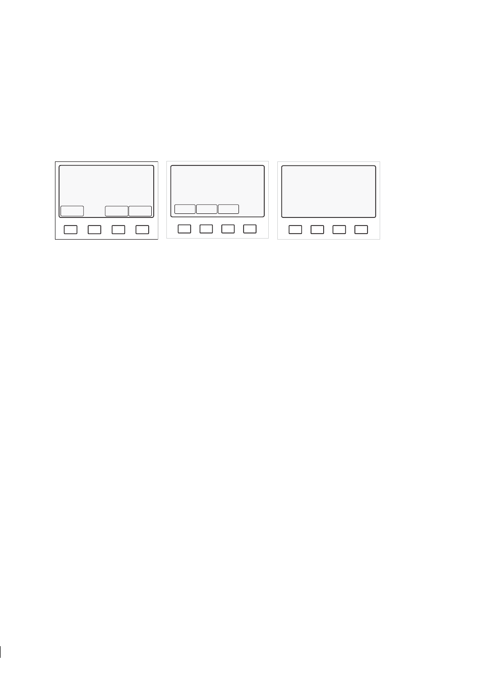
Press the key D (soft key Display) for additional data, e.g. output in mA. Further data is obtained in the
Information display by soft keys Optical image (Figure 5.3), System configuration and Sensor
head
. Return to Normal display by pressing the RESET key as many times as necessary.
Note:
Use the keyboard’s keys A, B, C, D for the soft key commands, do not touch the display screen (see
Section 5.3.1).
A
B
C
D
CONC
36.7%
TEMPERATURE: 30.2 °C
86.4 °F
STANDARD RI(25°C): 1.3960
TEST: 133.6
Normal operation
Optical
image
System
configur-
ation
Sensor
head
Output signal: 16.7 mA
A
B
C
D
RI(25ºC
1.4412
PR-03 version 8.5
Sensor interface version 4.0
Sensor processor version 4.0
Relay unit not connected
External output unit not connected
Output: 4..20 mA = 1.4260..1.4900 RI(25
Relay
configur-
ation
Switch
configur-
ation
Wash
times
A
B
C
D
RI(25ºC
1.4412
SENSOR HEAD
Head temperature: 20 ºC
Head humidity: 32 %
Normal operation
Information display
System configuration display
Sensor head display
Figure 5.3
Getting additional information
Measure the output signal. It should agree with the mA display.
If there are problems in the system check, proceed to Chapter 7, “Troubleshooting and correcting problems”.
5.2.1 Checking accessory units
All the accessory units, both relay units -WR and PR-7080 and external output unit, have two indicator
LEDs that tell about their status. Open the enclosure cover to see these LEDs. When the refractometer
system is on and the IT-R is finished with the initial check (i.e. the Normal display has appeared, see at
page 29), only the green led should be lit. If the red led stays lit, there’s problem in the accessory unit
configuration, see Section 5.7 and Section 5.8.
Note:
When the refractometer system is powering up, both LEDs light up for a short time during the system
check. After a while the red led should be turned off, in a working system only the green led is lit.
5.2.2 Testing prism wash
Important:
Before you test prism wash, check that there is liquid in the pipe in front of the refractometer
and that the steam washing parts are properly installed and connected.
If you are using prism wash controlled by a relay unit check the wash sequence by pressing in the Nor-
mal display soft key Start prism wash (Figure 5.2). The TEST value should clearly increase (and the
concentration reading decrease) during wash.
Note:
The manual wash command cannot override External hold (see Section 5.6).
Note:
The Start prism wash soft key appears in the Normal display only when a relay has been con-
figured as wash relay (Section 5.7). In demo mode it never appears, because the external units have been
disconnected.