6 configuring input switches, Ab c d – K-Patents PR-03 User Manual
Page 42
42
42
42
42
36
PR-03 instruction manual
A
B
C
D
Diagnos-
tics
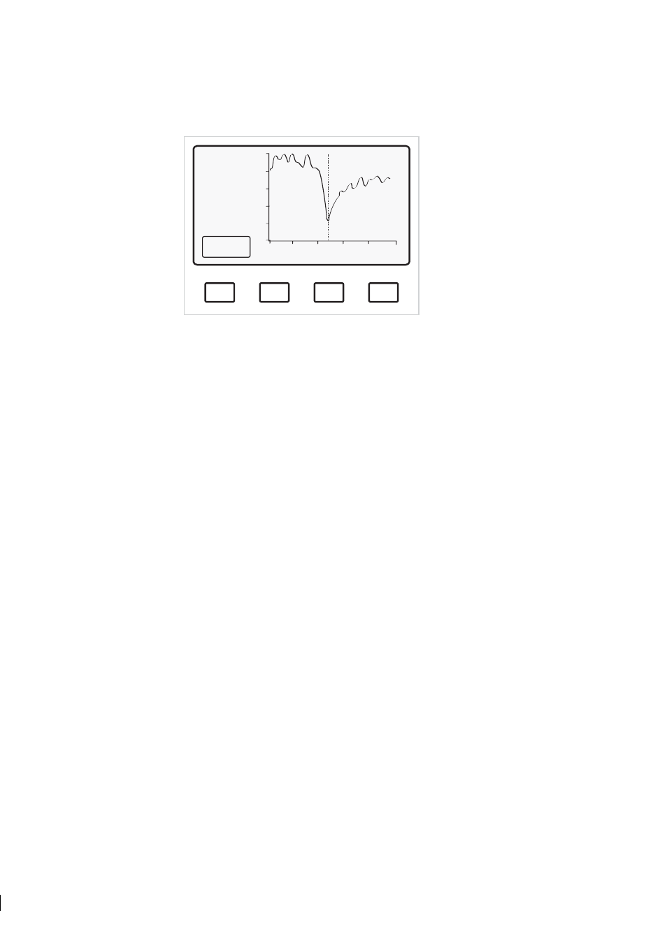
SLOPE
TEST: 115.7
31.2
°C
Max: 208
Slope: 2.7
Endp: 21
L): 10.1
R(: 25.8
Normal operation
Figure 5.9
Slope display
Max:
The filtered value of the maximum light intensity RMX of the raw data (Figure 5.7).
Slope:
The absolute value of the slope curve dip at TEST. The value of Slope must be above 1 to be
acceptable.
5.5.5 Viewing Image diagnostics
The Image diagnostics display lists the critical values for TEST acceptance:
Max intensity OK (above 100)?
Yes/No
Endpoint below 75 %?
Yes/No
Image below corner?
Yes/No
Slope OK (above 1)?
Yes/No
Left curve OK (above 1)?
Yes/No
Right curve OK (above 1)?
Yes/No
For measurement with a normal sample, all answers should be Yes. A message Dip in image may
appear if the optical image is irregular.
5.6 Configuring input switches
To reach the input switch configuration settings from the Normal Display, use the command sequence
Calibrate/Parameters/Switch inputs
.
The microprocessor accepts four switch inputs: A, B, C and D (for connections see 3.10). The function of
each switch can be individually defined from one of the following five alternatives:
0
Not defined
(factory setting).
1
Scale select
Select parameters for alternative process mediums. There are all to-
gether four alternative mediums selectable by closure of the corre-
sponding switch. If no selection switch is closed, the normal medium
is selected. Maximum number of mediums is five (Normal, A, B, C,