Kreg Swing Stop User Manual
Swing stop, Instructions, Attaching accessories
R
Swing Stop
™
Instructions
Cutting numerous pieces to the exact length, without measuring, is
easy. Gently press the end of the board opposite the blade against
the side of the Stop Arm; as shown in
Figure 1.
Thank you for purchasing this Kreg Precision Machine Accessory.
The Swing Stop
TM
provides an easy and effi cient method for making
incredibly precise cuts, one after another.
Shop Made Table
Workpiece
Miter Saw
Fig. 2
These stops can be secured anywhere along the trak. The Swing
Stop
TM
is specifi cally designed to raise out of your way automatically,
when a board is pushed against the front; as shown in
Figure 2.
The Stop Arm rests on top of the workpiece until the board has been
withdrawn. When the board is removed or moved to the side of the stop,
the arm drops down and is again ready for use.
The Stop Arm can be positioned on either side of the base which is
secured to the Top Trak with the T-Knob. (
The Stop Arm should be
positioned between the base and the saw blade; as shown in Figure 2.)
The distance between the blade and the Stop Arm is measured using
the lens, and tape attached to the Top Trak. (see the opposite side of
this page for more instructions.)
Production
Stop
Swing Stop
TM
Stop Base
Lens
Tape
Top Trak
Stop Arm
5/2010 FT4125
Rev C
#KMS7801
Fig. 1
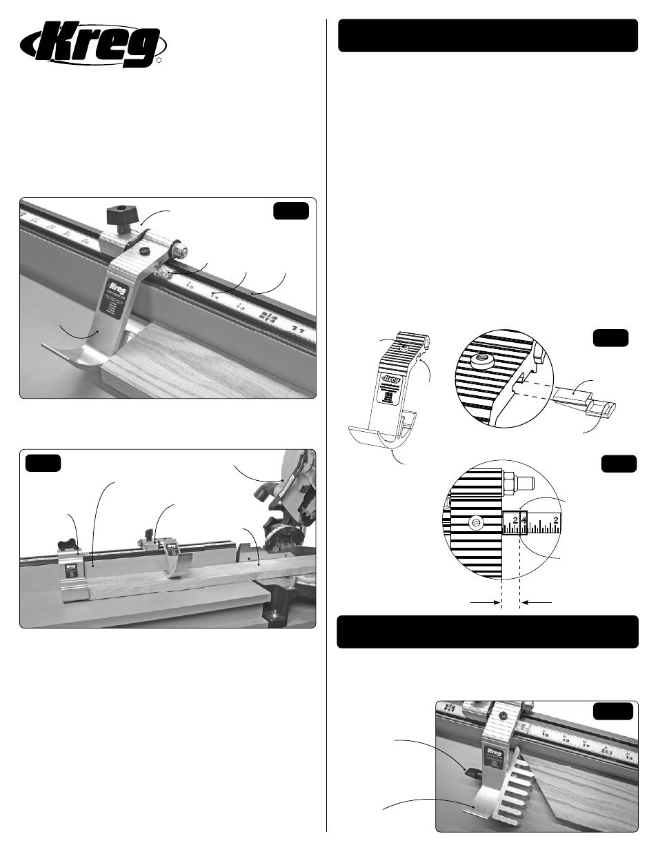
Attaching Accessories
The Swing Stop
TM
has a “fi nger” which is just behind, and parallel to,
the Stop Arm. The space between the Stop Arm and “fi nger” will accept
a 1/4-20 bolt for attaching accessories such as the Miter Attachment
(KMS7831); as shown in Figure 5.
1/4-20
Bolt Knob
Miter
Attachment
Fig. 5
About the Lens
Our stops feature an adjustable lens cursor, similar to the lens on a
quality tablesaw rip-fence. The Lens is a clear material, except for a red
line (cursor) on the bottom of the Lens; as shown in Figure 3. The Lens
is adjustable to fi ne-tune the stop, and is secured in place with the Lens
Screw. The Lens can be aligned to either side of the Stop Arm.
The Cursor makes it easy to read the tape lines and compensate for
variations in blade thickness and imperfectly positioned tape. Because
the Lens Cursor protrudes 3/8” from the stop (as seen in Figure 4), the
self-adhesive tape on a Kreg Precision Measuring Component must be
placed 3/8” closer to the saw blade for the lens to work properly. If you
are using another brand of track/tape that is not offset for use with the
lens, you may remove the lens and read the measurement directly off
the edge of the stop.
After you have correctly set the Swing Stop
TM
for your particular set up,
you may make a few practice cuts to ensure its accuracy. First, set the
Swing Stop
TM
at 20” (or any length you desire) and make a cut. Check
the stock with your tape measure to test the accuracy of the cut. At
this time you may make adjustments to the Lens as necessary. Do this
by loosening the Lens Screw and gently pulling or pushing the Lens to
its desired location before tightening the Lens Screw again. Make a
second cut at 18” (or any length shorter than the original) and test its
accuracy again. Repeat this process as necessary.
3/8”off-set
Red Line
Cursor
Read Tape
Here
Fig. 3
Fig. 4
Red Line Cursor
Lens
Stop Arm
Lens Slot
Lens Screw
WARNING: This product contains one or more chemicals known
to the State of California to cause cancer and birth defects or other
reproductive harm. Wash hands after handling.