Legrand inQuire 1000 User Manual
Page 11
301 Fulling Mill Road, Suite G
© Copyright 2006 by On-Q/Legrand Inc.
Page 18
Middletown, PA 17057
All Rights Reserved
(800)
321-2343
www.onqlegrand.com
NOTE: Only door release devices that operate using 12V DC and
have a maximum current draw of 500mA are to be used with the
inQuire™ 1000 Intercom System.
•
Insert the Intercom Module into the mounting bracket and insert the
bracket into the On-Q enclosure. Secure the Intercom Module to the
bracket by depressing each plunger at each corner of the Intercom
Module.
•
DO NOT apply power to the Intercom Module until all RJ45 plugs
are seated in the correct jacks on the Intercom Module.
•
Plug in all RJ45 connectors for Room and Desktop Units into the
appropriate jacks on the Intercom Module according to your cable
labeling.
•
If utilized, plug the RJ45 connector for the Patio Unit into the jack
labeled "11/PATIO UNIT" on the Intercom Module.
•
The Main Console Unit cables should plug into the correct MAIN
jacks according the the cable labeling.
•
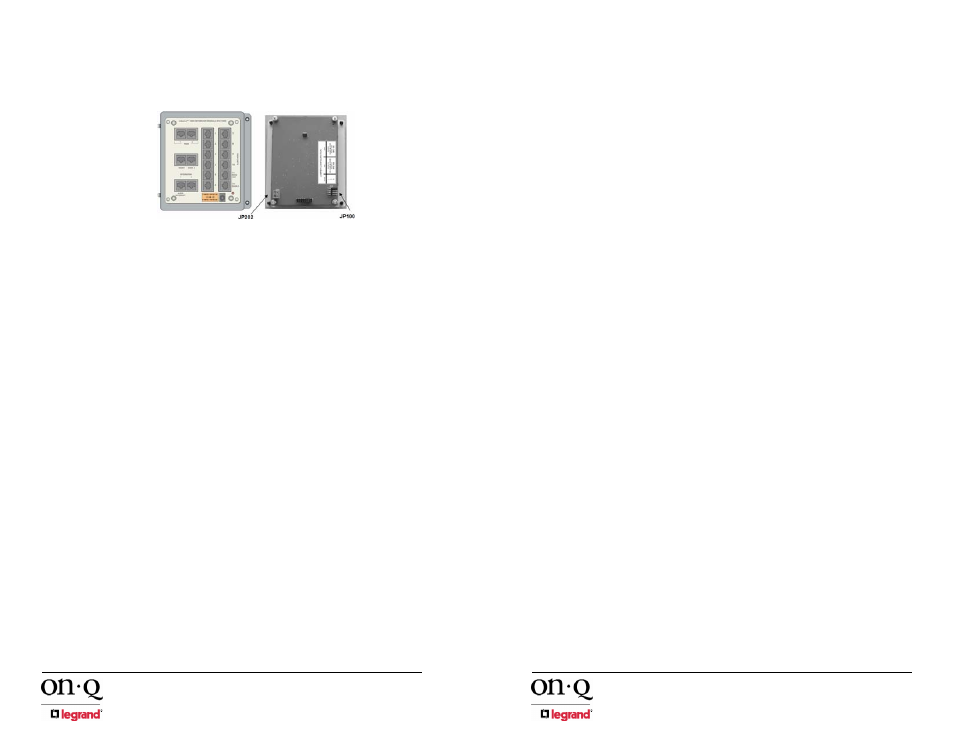
If 3 total Door Units will be used then the third Door Unit cable must
plug into the jack labeled 12/DOOR 3 on the Intercom Module and
you must remove a shorting block from pin #1 of JP100 on the rear
of the Intercom Module (see Figure 11).
•
Pin #2 of JP100 controls whether you want to hear the chime sound
associated with the optional Door Chime at the Door Unit or not. If
you do want to hear the Door Chime at the Door Unit when the
doorbell button is pressed, remove the jumper from pin #2 (see
Figure 11).
•
Pin #3 of JP100 is associated with Patio Unit functionality. If you are
using a Patio Unit, plug it into port #11/PATIO UNIT and remove the
jumper from pin #3 of JP100. This is also called “Security Mode”,
and allows the Patio Unit to be temporarily disabled from the Main
Console by simultaneously pressing the TALK and DOOR
RELEASE buttons. If the jumper on pin #3 is left on, port #11 is
configured to support a standard Room Unit.
NOTE: For obvious security reasons, there is no door release
function enabled on a Patio Unit.
•
Apply power to the Intercom Module and verify system functionality.
Figure 11 - Install Intercom Module into Enclosure
301 Fulling Mill Road, Suite G
© Copyright 2006 by On-Q/Legrand Inc.
Page 7
Middletown, PA 17057
All Rights Reserved
(800)
321-2343
www.onqlegrand.com
•
To avoid damage from debris during or after construction, use an
enclosed gang box.
•
The 3 gang box should be installed at the same height as electrical
switch boxes in the home.
•
A total of TWO Cat 5e runs are required to operate the Main
Console Unit.
• Run
TWO Cat 5e cable runs from the 3 gang box directly to the
enclosure where the Intercom Module will be installed. You must
label both ends of the cable runs for the Main Console Unit to
ensure proper termination during the trim-out. Label one cable
"Main 1" and the other cable "Main 2". Follow the wiring guidelines
listed in this manual to ensure a quality cable installation.
2. Room
Unit(s)
The procedure to rough-in the Room Unit(s) is as follows:
•
Typically the Room Unit(s) will be installed on the same wall as the
door to the room. Verify each Room Unit location with the
homeowner before proceeding. Avoid installing Room Units in the
same stud cavity on opposite sides of the wall to prevent feedback
problems.
•
The Room Unit mounts in a standard 2 gang electrical box. The use
of an enclosed box rather than an open mud ring will help minimize
the potential for feedback between units.
•
Any UL approved metal or plastic gang box can be used.
•
To avoid damage from debris during construction or after
construction, use a gang box that will completely enclose the unit.
•
The 2 gang box should be installed at the same height as the
electrical switch boxes in the home.
•
ONE Cat 5e run is required to operate the Room Unit.
• Run
ONE Cat 5e cable from the 2 gang box directly to the
enclosure where the Intercom Module will be installed. Label both
ends of your cable run to indicate Room Unit number (ex: "Room
Unit 5). Follow the wiring guidelines listed in this manual to ensure a
quality cable installation.
•
Repeat these instructions for each and every Room Unit that will be
installed in the system (maximum of 12).
3. Desktop
Unit(s)
The procedure to rough-in the Desktop Unit(s) is as follows:
•
Typically the Desktop Unit(s) will be connected to a Cat5e outlet on
a wall where the desk or nightstand will be placed.. Verify each
Desktop Unit location with the homeowner before proceeding
•
The Cat 5e outlet for the Desktop Unit typically mounts in a
standard 1 gang electrical box or mud ring.
•
Any UL approved metal or plastic gang box can be used.
•
The 1 gang box should be installed at the same height as the
electrical outlet boxes in the home.