Legrand inQuire 1000 User Manual
Page 12
301 Fulling Mill Road, Suite G
© Copyright 2006 by On-Q/Legrand Inc.
Page 8
Middletown, PA 17057
All Rights Reserved
(800)
321-2343
www.onqlegrand.com
•
ONE Cat 5e run is required to operate the Desktop Unit.
• Run
ONE Cat 5e cable from the 1 gang box directly to the
enclosure where the Intercom Module will be installed. Label both
ends of your cable run to indicate Desktop Unit number (ex:
"Desktop Unit 5). Follow the wiring guidelines listed in this manual
to ensure a quality cable installation.
•
Repeat these instructions for each and every Desktop Unit that will
be installed in the system (maximum of 12).
4. Patio
Unit(s)
The procedure to rough-in the Patio Unit(s) is as follows:
•
Typically the Patio Unit(s) will be installed on the exterior of the
home next to a patio door. Verify the Patio Unit(s) location(s) with
the homeowner before proceeding.
•
Since the Patio Unit will most likely be installed on the exterior of
the home and will be exposed to weather conditions, these
instructions must be followed to ensure a quality installation.
Brick or other cement-based material exteriors:
•
The recommended box to use is a 2 gang outdoor
weatherproof box. This box should be of the type that is
made of heavy die-cast aluminum. Using a heavy die-cast
aluminum box will provide adequate strength in a brick or
cement-based exterior.
Vinyl or wood based siding material exteriors:
•
If possible, use a heavy duty die-cast aluminum 2 gang
box if it can be securely mounted to the interior framing. If
this is not possible then it is recommended that you use a
heavy duty metal 2 gang box that can be securely
mounted to the interior framing of the home.
•
To ensure the 2 gang box that will be used to house the Patio Unit
is roughed in correctly, communication with the building contractor
who is responsible for the exterior finish of the home is highly
recommended.
Brick or other cement-based material exteriors:
•
The masonry contractor must be provided with specific
instructions as to how the 2 gang box should be installed
including location, correct positioning, and proper depth.
•
If possible, clearly mark this information on the home's
exterior insulation board or vapor barrier material to serve
as a reminder to the mason.
•
The correct positioning of the 2 gang box may not be
obvious to the masonry contractor. Ensure that the
masonry contractor knows which edge of the box is up
and which edge is down so that the Patio Unit can be
installed in the correct vertical position.
301 Fulling Mill Road, Suite G
© Copyright 2006 by On-Q/Legrand Inc.
Page 17
Middletown, PA 17057
All Rights Reserved
(800)
321-2343
www.onqlegrand.com
•
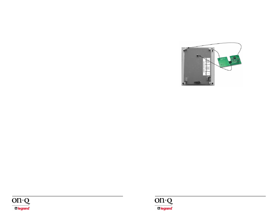
Place the Door Chime circuit board on the rear of the Intercom
Module so that the two mounting holes on the Door Chime circuit
board are seated on the Intercom Module threaded mounting studs
(see Figure 10).
•
Ensure that the Door Chime's pin array socket is properly aligned
with the pin array (labeled JP203) on the Intercom Module.
•
Apply slight downward pressure to the Door Chime circuit board to
securely seat the pin aaray connections together.
•
Use the included hex nuts and washers to secure the Door Chime
circuit board to the Intercom Module mounting studs.
7. Intercom
Module
The procedure to install the Intercom Module is as follows:
•
Terminate all cable runs from Room Units, Desktop Units, Patio
Units, Door Units, and the Main Console Unit using RJ45 plugs.
Follow the T568A wiring standard which can be found in this
manual.
NOTE: The proper termination of the RJ45 plugs is critical the
correct operation of the inQuire™ 1000 Intercom System. Incorrect
termination could result in damage or improper operation of the
system.
•
If you are using a door release device then you must terminate the
two conductors from your door release device to the Intercom
Module by routing the conductors through the mounting bracket
before inserting the Intercom Module into its mounting bracket.The
door release device conductors are to be terminated to the blue
mounting block (JP202) located on the rear circuit board of the
Intercom Module. Maintain correct polarity (see Figure 11).
Figure 10 - Install Door Chime