Legrand inQuire 1000 User Manual
Page 16
301 Fulling Mill Road, Suite G
© Copyright 2006 by On-Q/Legrand Inc.
Page 12
Middletown, PA 17057
All Rights Reserved
(800)
321-2343
www.onqlegrand.com
B.
Final Wiring (Trim-Out)
.
The trim-out of the system should be completed after wall coverings have
been finalized. The following section will instruct you on the proper methods to
finish the installation of the various inQuire™ 1000 Intercom System
components.
1.
Main Console Unit
The procedure to trim-out the Main Console Unit is as follows:
•
Locate the Cat 5e cable in the roughed in 3 gang box that you
labeled as "Main 1".
•
Strip back approximately 2" of insulation from the Cat 5e cable.
•
Untwist cable pairs and place them next to each other in color-
coded order according to theT568A standard and insert the wires
into an RJ45 plug.
•
Crimp the cable into the RJ45 plug with a proper RJ45 crimp tool.
•
Plug the terminated "Main 1" cable into the RJ45 jack on the rear of
the Main Console Unit "Main 1" (see Figure 4).
•
Repeat the previous steps for the cable labeled "Main 2".
•
Insert the Main Console Unit and the Cat 5e cables into the 3 gang
box and secure the unit to the box using the 6 included screws.
Attach a 3 gang decor plate to the unit to complete the installation.
•
Terminate the other end of each labeled Cat 5e cable in the
enclosure and plug the "Main 1" cable into the jack on the Intercom
Module labeled "MAIN 1" and plug the "Main 2" cable into the jack
on the Intercom Module labeled "MAIN 2".
•
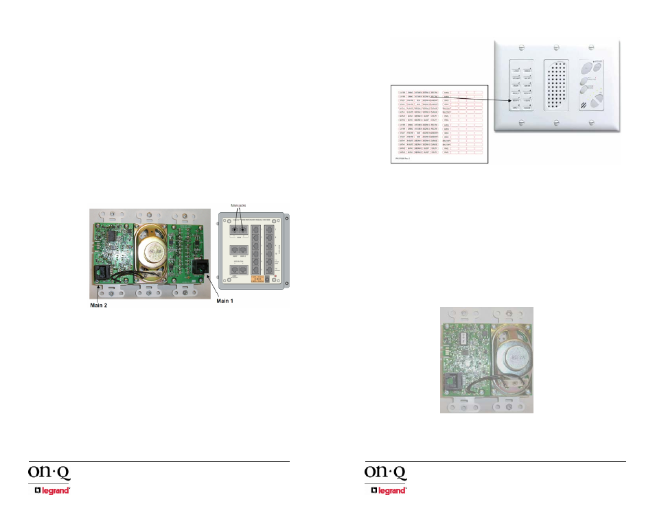
Once all Units have been trimmed-out, use the provided location
labeling sheet (R1596) to label each location in the status section
on the front of the Main Console (see Figure 5). This really helps
make your system installation much more professional.
Figure 4 - inQuire™ 1000 Intercom System Trim-Out Phase
301 Fulling Mill Road, Suite G
© Copyright 2006 by On-Q/Legrand Inc.
Page 13
Middletown, PA 17057
All Rights Reserved
(800)
321-2343
www.onqlegrand.com
2. Room
Unit(s)
The procedure to trim-out the Room Unit(s) is as follows:
•
Locate a Cat 5e cable in a roughed in 2 gang box labeled as "Room
Unit X" (X is the Room Unit number).
•
Strip approximately 2" of insulation from the Cat 5e cable.
•
Untwist cable pairs and place them next to each other in color-
coded order according to theT568A standard and insert the wires
into an RJ45 plug.
•
Crimp the RJ45 plug onto the cable with a proper RJ45 crimp tool.
•
Plug the terminated "Room Unit X" cable into the RJ45 jack on the
rear of the Room Unit (see Figure 6).
Figure 5 - Label Each Location on Main Console
Figure 6 - Plug Room Cable into Room Unit