Cable connections, Mixer settings, Cable connections mixer settings – Lynx Studio LynxTWO User Manual User Manual
Page 21
Page 21
TWO
LynxTWO Master
TWO
LynxTWO Slave 1
TWO
LynxTWO Slave 2
Internal Clock Cable
Configuring Multiple LynxTWO’s
4.
Listen to the playback of any wave file and note which LynxTWO card is generating
the audio signal. In this case, the card generating audio is adapter 1.
5.
Repeat steps 3 and 4, for “LynxTWO 2 Play 1”, “LynxTWO 3 Play 1”, and so on
until all LynxTWO’s in your system have been identified.
The next step is to choose which LynxTWO will act as a master. This choice is based
on preference only, but for ease of connection it makes sense to choose a LynxTWO
that is on one end of the PCI slot array on your motherboard.
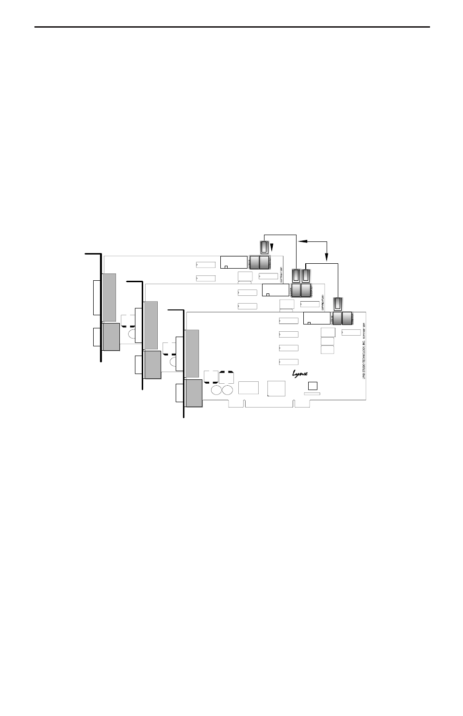
Cable Connections
Starting with the master LynxTWO, insert the plug on one end of a Lynx Internal Clock
Cable into the CLOCK OUT header, until it clicks and locks into place. This header is
polarized to ensure the correct orientation of the cable plug. Insert the plug on the free
end of the cable into the CLOCK IN header, on the nearest slave LynxTWO. Connect
each slave in a similar manner. Refer to the figure below.
Alternatively, if clock connections are made externally using the SYNC IN and CLOCK
OUT connectors on the L2Sync cable, use BNC cables to make connections between
cards in the same sequence as described above.
Mixer Settings
With the clock connections in place, the sample clock settings of each LynxTWO must
be adjusted using the LynxTWO Mixer.
For the master LynxTWO:
1.
Select the master LynxTWO from the Mixer pull-down menu.
2.
Select a desired Sample Clock Source.
3.
Select a desired Sample Clock Reference.
For each slave LynxTWO:
1.
Select the slave LynxTWO from the Mixer pull-down menu.
2.
Set the Sample Clock Source to Header if internal clock connections are used or
External if external clock connections are used.
3.
Set the Sample Clock Reference to Word.