Connector pinouts, Page 31 – Lynx Studio LynxTWO User Manual User Manual
Page 31
Page 31
Connector Pinouts
L2Audio Port
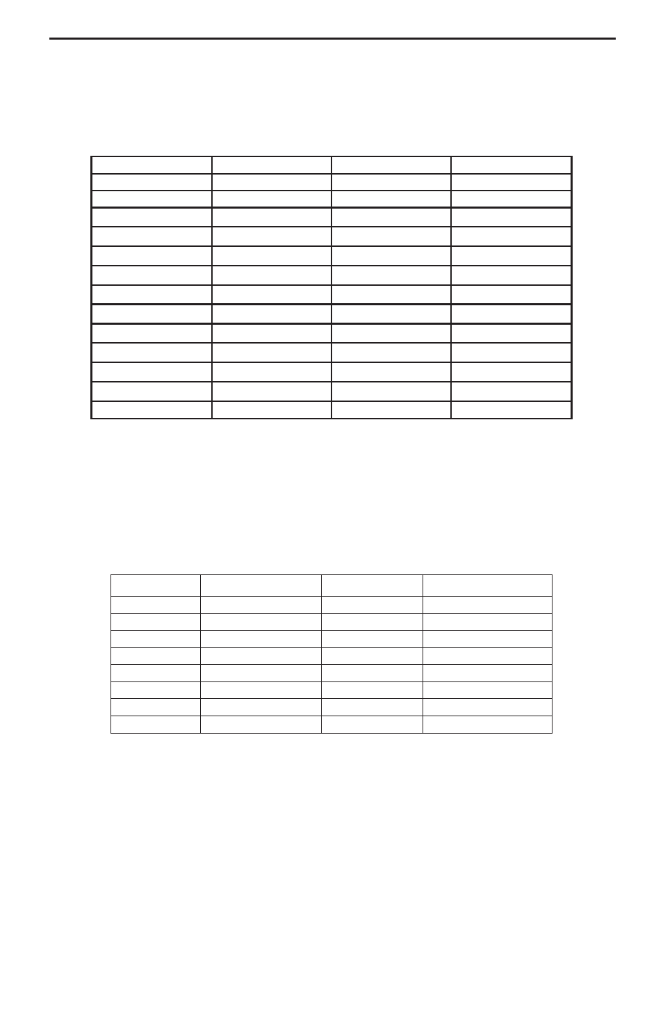
The L2Audio Port is a female 25-pin D-connector with the following connections:
n
i
P
l
a
n
g
i
S
n
i
P
l
a
n
g
i
S
1
t
o
H
4
T
U
O
4
1
d
l
o
C
4
T
U
O
2
d
n
G
4
T
U
O
5
1
t
o
H
4
N
I
3
d
l
o
C
4
N
I
6
1
d
n
G
4
N
I
4
t
o
H
3
T
U
O
7
1
d
l
o
C
3
T
U
O
5
d
n
G
3
T
U
O
8
1
t
o
H
3
N
I
6
d
l
o
C
3
N
I
9
1
d
n
G
3
N
I
7
t
o
H
2
T
U
O
0
2
d
l
o
C
2
T
U
O
8
d
n
G
2
T
U
O
1
2
t
o
H
2
N
I
9
d
l
o
C
2
N
I
2
2
d
n
G
2
N
I
0
1
t
o
H
1
T
U
O
3
2
d
l
o
C
1
T
U
O
1
1
d
n
G
1
T
U
O
4
2
t
o
H
1
N
I
2
1
d
l
o
C
1
N
I
5
2
d
n
G
1
N
I
3
1
e
n
o
n
The LynxTWO B Model replaces IN 3 and IN 4 with OUT 5 and OUT 6. The LynxTWO
C Model replaces OUT 3 and OUT 4 with IN 5 and IN 6.
L2Sync Port
The L2Sync Port is a female, high-density 15-pin D-connector with the following
connections:
n
i
P
l
a
n
g
i
S
n
i
P
l
a
n
g
i
S
1
9
t
o
H
t
u
O
l
a
t
i
g
i
D
2
0
1
d
l
o
C
n
I
l
a
t
i
g
i
D
3
+
n
I
C
T
L
1
1
4
+
n
I
c
n
y
S
2
1
5
t
o
H
n
I
l
a
t
i
g
i
D
3
1
+
t
u
O
C
T
L
6
4
1
+
t
u
O
k
c
o
l
C
7
d
n
G
C
T
L
5
1
d
l
o
C
t
u
O
l
a
t
i
g
i
D
8
d
n
G
k
c
o
l
C
Header Connectors
The LStream 2 port is a 14 pin header shrouded in black plastic labeled JP1.
The CLOCK IN port labeled JP2 and CLOCK OUT port labeled JP3 are two-pin
headers shrouded in black plastic. For both connectors, Pin 1 carries the clock signal
and Pin 2 is a ground signal. Pin 1 is located on the left side of each connector when
viewing the component side of the board.
Appendix