Part names and functions, Front panel, Rear panel – Marantz PM8004 User Manual
Page 7
4
ENGLISH
q
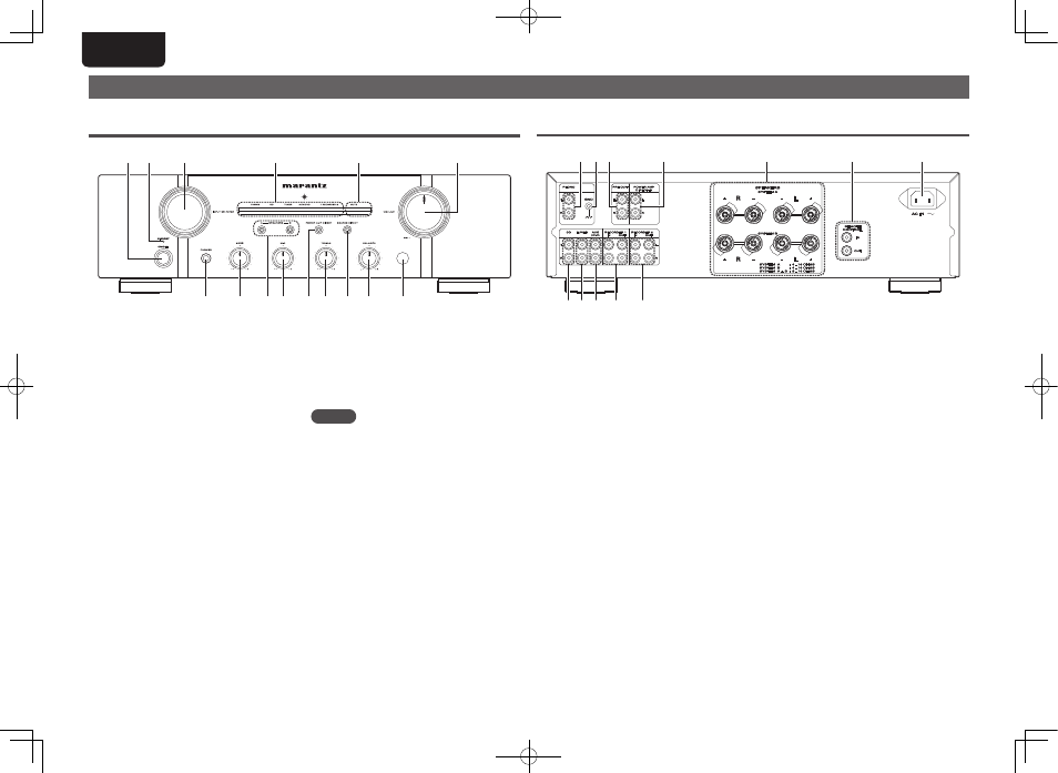
Power switch (ON/OFF) ······························· (8)
w
STANDBY indicator ······································ (8)
Indicates the status of the unit’s as follows:
• Power “ON” : Off
• When the protection circuit is activated :
Red (blinking) .............................................. (6)
• Standby : Red
• Power “OFF” : Off
e
INPUT SELECTOR knob ······························· (9)
r
Input indicators ············································ (8)
t
MUTE indicator (MUTE) ······························· (9)
y
VOLUME control knob ····························· (8, 9)
u
Remote control sensor ·························· (3, 10)
i
BALANCE control knob ···························· (8, 9)
o
SOURCE DIRECT switch/indicator ············· (9)
Q0
TREBLE control knob ······························· (8, 9)
Q1
POWER AMP DIRECT switch/indicator ······ (9)
Q2
MID control knob ······································ (8, 9)
Q3
SPEAKERS A/B switch/indicators ·············· (9)
Q4
BASS control knob ··································· (8, 9)
Q5
Headphone jack (PHONES) ·························· (9)
NOTE
You can adjust the
i
BALANCE,
Q0
TREBLE,
Q2
MID and
Q4
BASS control knobs only when
o
SOURCE DIRECT switch is turned off.
Part names and functions
For buttons not explained here, see the page indicated in parentheses ( ).
Front panel
t
q
w
e
r
i
Q1 Q0
Q2
Q4
Q5
y
u
o
Q3
q
PHONO input connectors ···························· (7)
w
PHONO GND terminal ·································· (7)
e
PRE OUT connectors ·································· (10)
r
POWER AMP DIRECT IN connectors ·········· (9)
t
Speaker system terminals
(SPEAKERES SYSTEM A/B) ···················· (6, 7)
y
REMOTE CONTROL
input/output connectors ··························· (10)
Rear panel
r
t
y
u
w e
q
i
o
Q0
Q1
Q2
u
AC inlet (AC IN) ············································· (8)
i
RECORDER 2
input/output connectors ····························· (7)
o
RECORDER 1
input/output connectors ····························· (7)
Q0
AUX/DVD input connectors ························ (7)
Q1
TUNER input connectors ····························· (7)
Q2
CD input connectors ···································· (7)
1.PM8004U_ENG_0701.indd 4
2010/07/01 17:46:11