Analog connections (balanced), Digital connection, Hot (+) gnd – Marantz SA11S3N User Manual
Page 16: Cold (-), Digital audio input, Digital audio output, N balanced jacks
9
ENGLISH
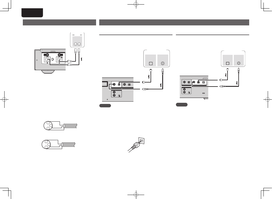
Analog connections (BALANCED)
BALANCED
HOT (+)
GND
L
R
ANALOG OUTPUTS
UNBALANCED
L
R
COLD (-)
BALANCED
R
L
IN
AUDIO
L
R
L
R
BALANCED
jacks
n BALANCED Jacks
The BALANCED jacks on this unit are equipped with XLR
connectors that are widely used on professional equipment.
Their features are listed below.
• The 3 pin construction enables the musical signal to be
transmitted as a balanced signal, with little effect from
external noise.
• The detachable locking mechanism minimizes connector
play and enhances connection reliability.
The XLR connector for professional use is internally wired
in either of the following two systems. This unit employs
the USA system.
• USA system (w PIN=COLD e PIN=HOT)
1
2
3 HOT
COLD
GND
• European system (w PIN=HOT e PIN=COLD)
1
2
3 COLD
HOT
GND
If a product that employs the European system is connected
with this unit via a balanced cable, the reproduced signal
may be phase-inverted.
To correct the inversion, set the “Phase” to “Inverted” at
the menu setting (vpage 24).
Digital connection
When connecting, use a commercially available optical digital cable or coaxial digital cable.
Digital audio input
If a device equipped with CD transport or digital audio output is
connected to this unit, this unit can be used as a D/A converter
(“Using as a D/A converter” (vpage 20).
REMOTE CONTROL
DIGITAL OUTPUT
IN
COAX.
OPT.
DIGITAL INPUT
COAX.
OPT.
USB
OUT
EXT.
INT.
OPTICAL
OUT
COAXIAL
OUT
Signal flow
CD transport /
Digital devices
Coaxial digital
connecting cable
(sold separately)
Optical digital connecting cable
(sold separately)
NOTE
• Linear PCM signals with a sampling frequency of 32 kHz,
44.1 kHz, 48 kHz, 64 kHz, 88.2 kHz, 96 kHz, 176.4 kHz, or
192 kHz can be input into this device.
• Do not input signals other than linear PCM signals, such as
Dolby digital, DTS, AAC etc. into this device. Doing so may
cause noise, which may cause damage to the speakers.
Signal flow
Digital audio output
Connect digital devices such as AV receivers and D/A
converters with the unit to enjoy digital audio output from the
unit.
REMOTE CONTROL
DIGITAL OUTPUT
IN
COAX.
OPT.
DIGITAL INPUT
COAX.
OPT.
OUT
EXT.
INT.
1
RODUCT“
OPTICAL
IN
COAXIAL
IN
AV receivers /
D/A converters
Signal flow
Signal flow
Optical digital connecting cable
(sold separately)
Coaxial digital
connecting cable
(sold separately)
NOTE
Signals on the HD layer of the Super Audio CD cannot be
output in digital output. Signals that can be output using digital
output are digital audio signals from audio CDs, CD-layers of
Super Audio CDs, USB, iPod, PC, COAXIAL, and OPTICAL.
n When connecting the optical digital output
connector with an optical transmission cable
(sold separately)
Match the shapes then insert firmly.
1.SA-11S3N_ENG_Final_0525.indd 9
2012/05/25 17:14:02