System description, Mtt-ops-1 – MEGA Corp. MTT-OPS-1 User Manual
Page 12
MTT-OPS-1
13 Nov 2013
SECTION 2
System Description
2-3
HYDRAULIC DRIVE MOTOR SPEED CONTROL
(CROSSOVER ASSEMBLY)
The hydraulic drive motor speed control (Crossover
Assembly) consists of a flow control valve, 2 hydraulic
manifolds, crossover hose and test ports.
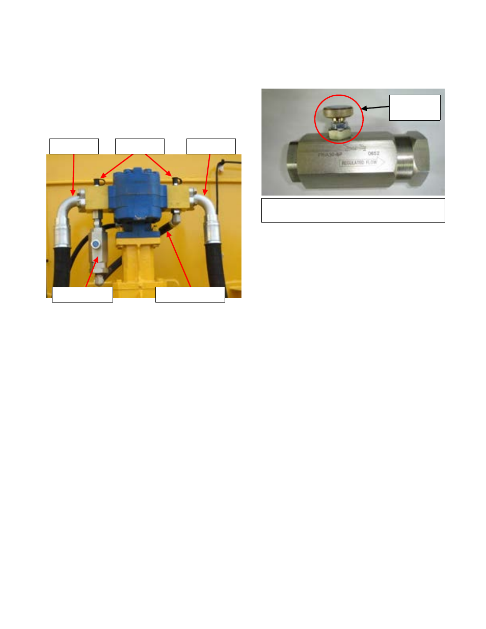
HYDRAULIC FLOW CONTROL VALVE
The hydraulic flow control is directional. The arrow on
the body indicates the direction of oil flow to meter
the bypassing oil. The adjusting knob on the valve
will allow adjustment of the oil flow to bypass the
drive motor, up to135 LPM (35 GPM) or up to
700 RPMs (RPM increase/decrease will vary
depending on the size of hydraulic drive motor the
unit is equipped with). If the flow control is reversed,
the flow control adjusting knob will not function and
the full flow capacity of the valve will bypass. This can
result in water pump rpm being below specifications
with no adjustment capability of the adjusting knob.
By turning the adjusting knob clockwise the
hydraulic oil that is bypassing will be reduced,
increasing the speed of the water pump. Turning the
knob counter-clockwise will increase the volume oil
being bypassed reducing the water pump speed. The
flow control valve is typically mounted on the
PRESSURE manifold of the hydraulic drive motor.
HYDRAULIC DRIVE MOTOR ACTIVATION
The hydraulic drive motor on MTT’s are typically
driven by the chassis hoist hydraulic system. The
activation can be controlled by the following;
Existing Electric Hoist Valve – The MEGA cab
control pump switch commands the hoist valve to
operate by sending an electric signal to the electric
solenoid on the hoist valve. This operates the hoist
valve, diverting the hydraulic oil to the water pump
drive motor.
Pilot Operated Diversion Valve – A remote
mounted diversion valve that receives an electric
signal from the cab control pump switch to activate a
pilot control to move a spool within the diversion
valve redirecting the hydraulic oil to flow to the water
pump drive motor. Typically this type of valve is
installed between the hoist pump and the
hoist valve.
Existing Mechanically Operated Hoist Valve –
Typically used on early model trucks with a
pneumatic system. This system is operated by the
cab control pump switch sending an electric signal to
an electric/pneumatic solenoid to control a
pneumatic cylinder. When the pneumatic cylinder
operates it moves the spool valve of the hoist valve to
divert hydraulic oil to the water pump drive motor.
PRESSURE
RETURN
TEST PORTS
FLOW CONTROL
CROSSOVER HOSE
Typical 135 lpm (35 gpm) Adjustable Hydraulic
Flow Control
ADJUSTING
KNOB