System description, Mtt-ops-1 – MEGA Corp. MTT-OPS-1 User Manual
Page 17
MTT-OPS-1
13 Nov 2013
SECTION 2
System Description
2-8
INTMNT (Intermittent Function)
Intermittent spray function sends request for
adjustable timing of spray head and dump bar as
commanded by the tON and tOFF dials.
Intermittent will only operate if at least 1 discharge
function (spray head or dump bar) switch is
activated. Water discharge can be stopped at any
time when in INTMNT mode by turning discharge
function switches OFF. The timer will continue to
cycle even if no water is being sprayed
The tON and tOFF adjusting knobs command timing
as follows:
•
t ON – Adjusts spray head ON time.
•
t OFF – Adjusts spray head OFF time.
The relationship between dial rotation and ON/OFF
time is as follows:
–
zero to 3 o’clock position: 3 sec to 15 sec
–
3 o’clock to max position: 15 sec to 30 sec
The above time ON/OFF scale applies to firmware
versions 3.7.0 and above. For firmware versions 3.6.x
and below, the range is 5 seconds to 30 seconds,
scaled linearly across the rotation of the dial.
The intermittent function will turn selected spray
head or dump bar on and off. Duration of tON and
tOFF cycle times are selected by setting the
appropriate dials on the master switch box. When the
INTMNT switch is ON and functions are selected, the
operator will observe different switch LEDs
conditions to indicate operation within the tON and
tOFF cycles. When a selected function switch (spray
head or dump bar) is operating during an ON cycle,
the selected function switch LED will be illuminated
as well as the INTMNT switch LED. When the INTMNT
cycles automatically to an OFF cycle, INTMNT switch
and function switch LEDs will extinguish. As the ON
cycle is about ready to engage, the INTMNT switch
LED will flash 3 times at the end of the OFF cycle to
indicate the selected spray functions are about to be
turned ON. These light conditions will change back
and forth until intermittent or function switches are
turned off.
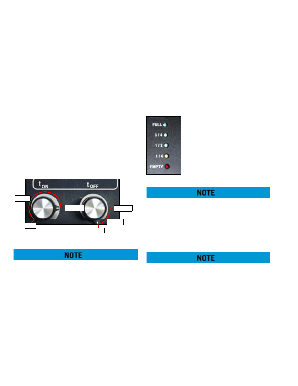
Water Level Indicator – Indicates tank water level as
sensed by the water level pressure
sensor in the rear of the water tank.
When the red EMPTY LED light
flashes, the tank is at minimum
water level. This low level signal is
also sent to the logic control to
automatically ramp-down the water
pump to prevent component
damage. Water pump operation can
only be restored if sufficient water is
in tank to extinguish EMPTY light.
In order to re-activate the water pump after low-
water shut-off, first fill the water tank with sufficient
water capacity to permit pump operation. Then turn
the PUMP and POWER switches OFF. Cycle the chassis
ignition key OFF/ON. Wait for the Master Switch Box
to complete its lights check. Then, if the water level
gauge reads above EMPTY, turn the POWER and the
PUMP switches on.
Certain terrains and water level fluctuations may
allow low water protection to capture a low water
level condition, causing the pump ramp-down. If
conditions allow water pump activation after water
level/terrain fluctuations have ceased, then the water
pump may be re-activated by following the steps in
the previous note.
Pressure Discharge Function Descriptions:
Spray Heads – Control opening or closing of the
associated valve when selected, or automatically
controlled when INTMNT function is selected.
Dump Bar (Pressure) – Controls opening or closing
of the BFV when selected, or automatically controlled
when INTMNT function is selected.
3s - 15s
zero
max
15s - 30s
3 o’clock
3 o’clock