System description – MEGA Corp. MTT-OPS-1 User Manual
Page 16
MTT-OPS-1
13 Nov 2013
SECTION 2
System Description
2-7
Once the logic control panel output is processed, the
logic control sends a feedback signal back to the cab
control box to illuminate the LED on the selected
function switch. If the switch LED does not illuminate,
a malfunction may exist in the logic control, wiring
harness or cab control box.
If a function switch is depressed with no
corresponding switch LED, check to ensure system
power switch is ON and the water level empty LED is
not flashing. If the switch LED is not illuminated, a
malfunction may exist.
If the selected function switch LED illuminates and
the component on the water tanker is not
functioning, the component (water-way valve, spray
head or water cannon) may have malfunctioned.
As functions are turned on and off, the water pump
switch will remain illuminated unless all spray system
functions (water-way valves, spray heads or water
cannon) are turned off. The logic control will
automatically turn the water pump off if all valves are
closed to prevent over-temp of the water pump
volute case. As the water level of the tank drops and
the EMPTY LED begins to flash, the logic controls will
deactivate the water pump to prevent cavitation or
dry running of the water pump.
WATER PUMP PROTECTION FEATURES
Soft Start and Stop – The water pump is protected
from sudden starts and stops whenever the pump is
turned ON or OFF via the switch or any auto/logic
control feature. This is accomplished by the logic
control system slowly commanding the appropriate
proportional hydraulic control valve to open or close
slowly to prevent hard starts or stops that can reduce
water pump service life.
Low Water Protection – The water pump is
automatically turned off by the logic control system
when a low water condition is detected. The logic
control system monitors tank water level and
commands the water pump to turn off when a
predetermined low water condition is noted. This
prevents the water pump from running in a dry sump
that will over-heat shaft seals due to lack of water.
Continued use will damage the shaft seals.
No-Flow Conditions – The water pump is
automatically turned off after about 100 seconds,
whenever all water discharge valves are closed. The
logic control system monitors all discharge valves
and begins a TIME OUT cycle to turn off the water
pump after about 100 seconds. Any time a discharge
valve is opened during the timing cycle, the clock is
reset. This feature prevents the water from heating
up due to the water pump impeller spinning in a
sump with no flow. The heating of the static water
will also heat the water pump causing deterioration
of grease and premature bearing failure.
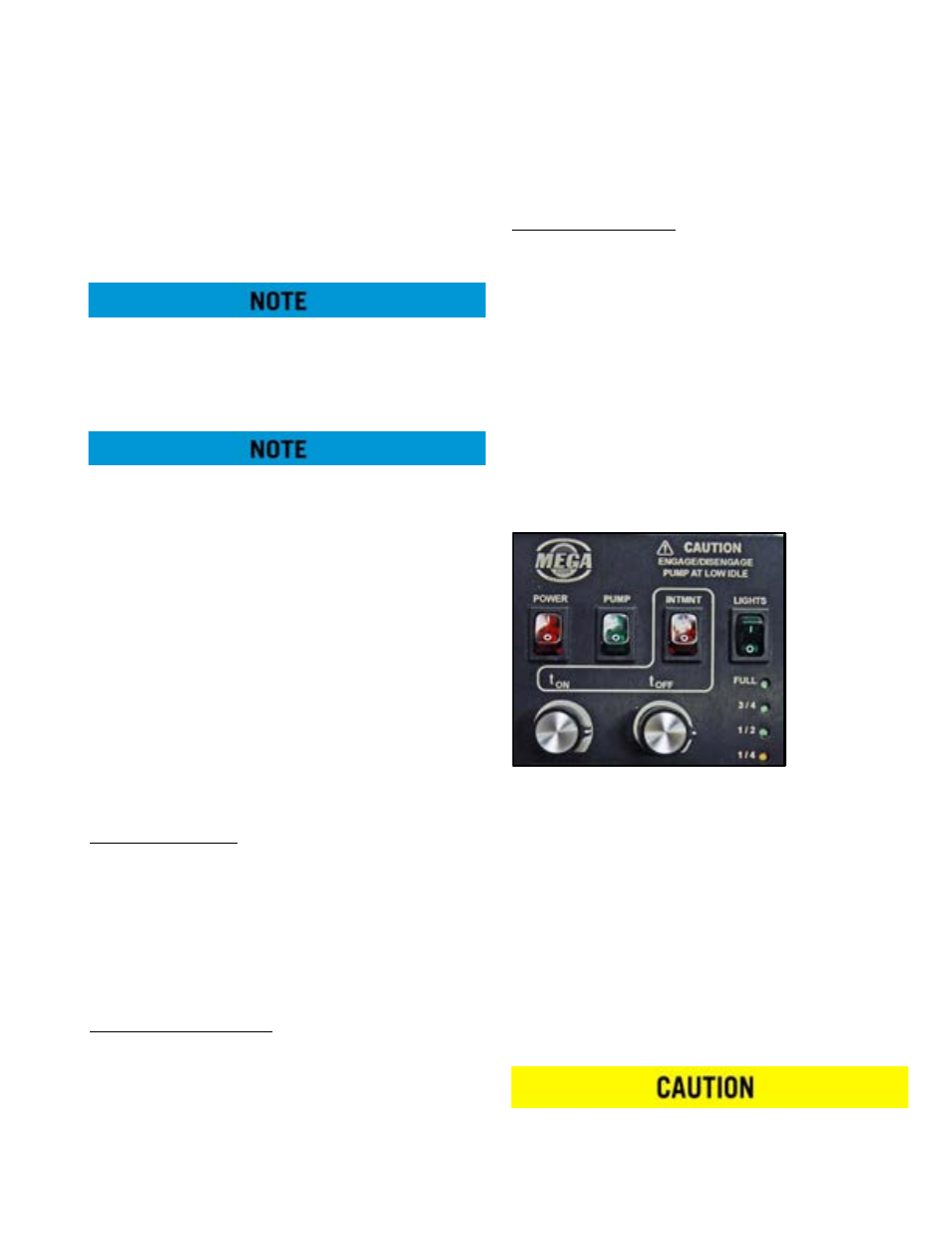
MASTER SWITCH BOX EXTENDED FUNCTION
DESCRIPTIONS
POWER – Turns POWER ON and OFF to cab controls
and digital controllers.
PUMP – Sends request for pump engagement/
disengagement to the digital control processor. The
digital controllers will activate the hydraulic circuit to
slowly ramp-up or ramp-down the water pump.
The water pump switch will flash whenever the
switch is on and the following conditions apply:
•
Low water condition is sensed (EMPTY LED is
flashing).
•
No flow condition is sensed (for about 100 sec-
onds, no waterway valves are open)
Engaging/disengaging the water pump above LOW
IDLE will result in water pump component damage
and reduced service life.