Counter input measurement, Default settings, Application notes – Measurement Computing CB-7080 User Manual
Page 10: Counter/frequency input mode selection, Default settings -6, Application notes -6, Counter/frequency input mode selection -6
CB-7080 & CB-7080D Counter/Timer User's Guide
Default settings
1-6
Counter input measurement
Perform the following procedure to measure the counter input. Refer to Figure 1-5 for the wire connection.
1. Power on and run the
test.exe
application.
2. Press
2
3. Press
$012
[Enter]
Receive=!01500600
4. Press
2
5. Press
$01B0
[Enter]
Receive=!01
6. Press
2
7. Press
#010
[Enter]
Receive=>????????
8. Press
2
9. Press
#011
[Enter]
Receive=>????????
In step 3: The status of CB-7080 is COUNTER mode
In step 5: Select non-isolated input
In step 7: Counter measurement of channel-0
In step 9: Counter measurement of channel-1
Note:
The command $01B101B1 that is referenced in step 7 can be used to select the isolated input. The commands
$01B2 and $01B3 are used for the other selections.
Default settings
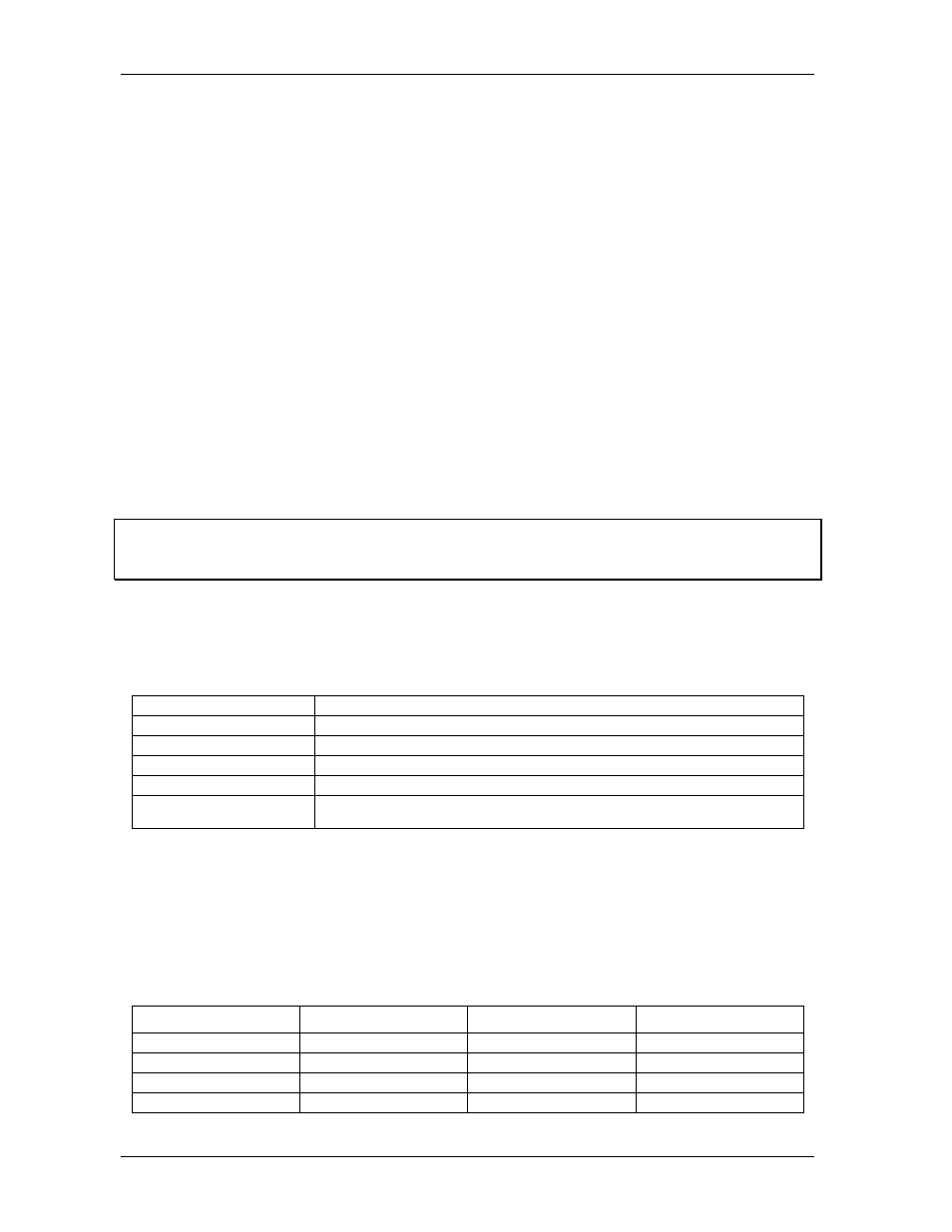
CB-7080 and CB-7080D default settings are listed in Table 1-2.
Table 1-2. Default Settings
Address
01
Baud rate
9600
Checksum
disabled
Data bits
1 start + 8 data + 1 stop (no parity)
Type
50 (counter input)
Alarm
CB-7080:
High alarm on counter 0 and counter 1
CB-7080D
Hi/hi-high alarm on counter 0
Application notes
Counter/Frequency input mode selection
Select the counter/frequency input from an isolated or non-isolated signal. Channel 0 and channel 1 can be
selected separately. Four different input modes are listed in the following table. These four input modes can
be used in both the CB-7080 and the CB-7080D.
Table 1-3. Counter frequency input
Input Mode
Command
Channel 0
Channel 1
Input mode 0
$AAB0
Non-isolated
Non-isolated
Input mode 1
$AAB1
Isolated
Isolated
Input mode 2
$AAB2
Non-isolated
Isolated
Input mode 3
$AAB3
Isolated
Non-isolated