Measurement Computing CIO-DAS16/M1 User Manual
Page 11
7
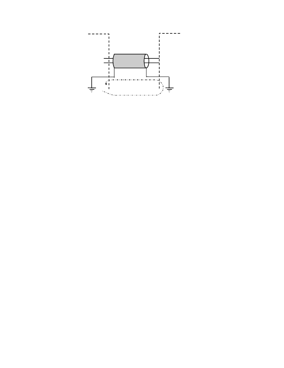
Figure 3-4. Wrong Way to Connect a Signal
3.3
DIGITAL OUTPUTS & INPUTS
All the digital outputs and inputs on the CIO-DAS16/M1 are TTL level. TTL is an electronics industry
term, short for Transistor Transistor Logic, which describes a standard for digital signals which are either
at 0V or 5V (nominal).
To control or sense any device other than TTL IC chips, please use appropriate signal conditioning, such
as solid state relays or electromechanical relays. See the Measurement Computing catalog for SSR-
RACK24 and CIO-ERB24 interface accessories.
3.3.1
Digital Output Connecto r
A second connector at the rear of the board contains signals from one 82C55 and one 82C54. The 24 bits
of digital I/O (82C55) and nine counter/timer signals (from three counters of an 82C54) are available to
the user for on/off control, pulse width and frequency measurement and general counting.
The 82C54 is a 10MHz (max) down-counter chip having three 16-bit counters. The input, gate and output
signals of the counters are brought out to the connector and on-board clock-select and chaining jumpers.
Together, the 24 digital I/O, and the counters use eight I/O addresses. The lower four (Base + 400,
through +403 are used for the 82C55 digital I/O and the upper four (Base + 404 through +407) are used
for the 82C54 user-counter timer.
3.3.2
Counter Clock Jumper
The board has a row of three jumpers adjacent to P5 that allow the 10 MHz [XTAL] OSCillator signal to
be connected to counter 0 input, and the counters to be chained 0 to1, and 1 to 2. In this way, a counter of
32 or 48 bits can be constructed from the three 16-bit counters of the 82C54. The counters can also be
chained externally via the 40-pin connector.
3.3.3
Cabling the Digital Conn ector
The digital/counter connector is a 40-pin header located at the rear of the CIO-DAS16/M1 board. It is
pinned out such that when connected to a 37-pin connector via a BP40-37, the 37-pin connector's pin-outs
are nearly identical to that of the CIO-DIO24/CTR3 (Figure 3-5). When using the BP40-37, the
digital/counter I/O connector is a 37-pin D-type connector accessible from the rear of the PC through the
Signal High
Signal Low
Channel # High
Channel # Low
Shielded Cable
CIO-DAS16/M1/16
LLGND
WRONG WAY! - This is the wrong way to connect cable shield.
Ground Loop Created Here
Instrument