Measurement Computing CIO-DAS16/M1 User Manual
Page 25
21
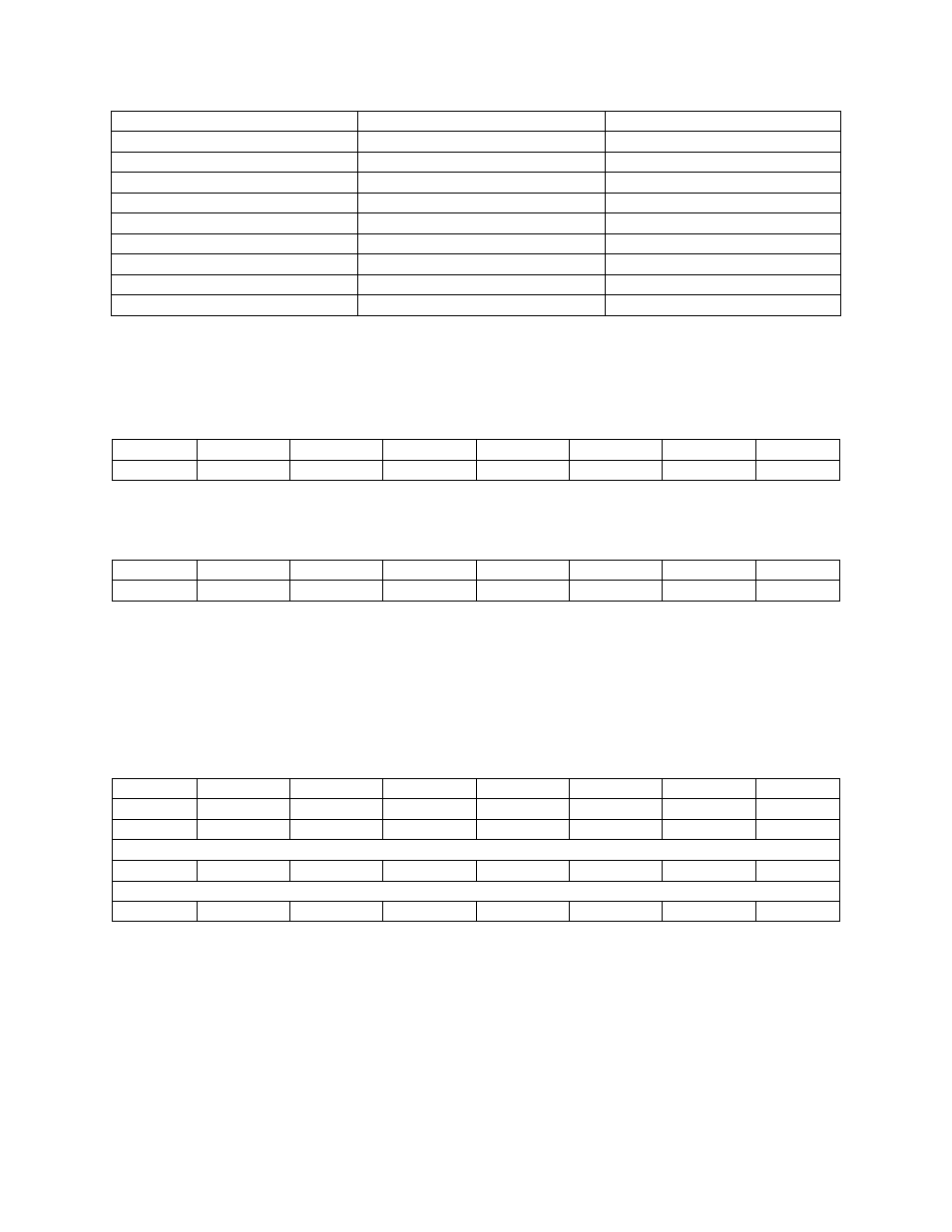
Table 4-4. Digital I/O and Counter Registers
ADDRESS
READ FUNCTION
WRITE FUNCTION
BASE +400h
Port A Input of 82C55 #1
Port A Output
BASE +401h
Port B Input
Port B Output
BASE +402h
Port C Input
Port C Output
BASE +403h
None. No read back on 82C55
Configure 82C55 #1
82C54 Counter Registers
BASE +404h
User Counter 0
User Counter 0 Load
BASE +405h
User Counter 1
User Counter 1 Load
BASE +406h
User Counter 2
User Counter 2 Load
BASE +407h
None. No read back on 82C54
Counter Control
4.6.10
82C55 Digital I/O Regist ers
PORT A DATA
BASE ADDRESS + 400h
7
6
5
4
3
2
1
0
A7
A6
A5
A4
A3
A2
A1
A0
PORT B DATA
BASE ADDRESS + 401
7
6
5
4
3
2
1
0
B7
B6
B5
B4
B3
B2
B1
B0
Ports A and B can be programmed as input or output. Each is written to and read from in bytes, although
for control and monitoring purposes, individual bits are used.
Bit set/reset and bit-read functions require that unwanted bits are masked out of reads and OR’ed into
writes.
PORT C DATA
BASE ADDRESS + 402
7
6
5
4
3
2
1
0
C7
C6
C5
C4
C3
C2
C1
C0
CH3
CH2
CH1
CH0
CL3
CL2
CL1
CL0
Bit Weight Decimal
128
64
32
16
8
4
2
1
Bit Weight HEX
80
40
20
10
8
4
2
1
Port C can be used as one 8-bit port of either input or output, or it can be split into two 4-bit ports which
can be independently input or output. The notation for the upper 4-bit port is PCH3 - PCH0, and for the
lower, PCL3 - PCL0.
Although it can be split, every read and write to port C carries eight bits of data so unwanted information
must be AND’ed out of reads, and writes must be OR’ed with the current status of the other port.