10 xtal – Measurement Computing CIO-DAS16/M1 User Manual
Page 6
2
2.2
USER-COUNTER CLOCK/CHAINING JUMPERS
The CIO-DAS16/M1 has three counters available to the user at the digital connector, P5. (A fourth
counter is available at the analog connector, P1.) The three digital-connector counters are associated with
registers Base + 404, +405, and +406.
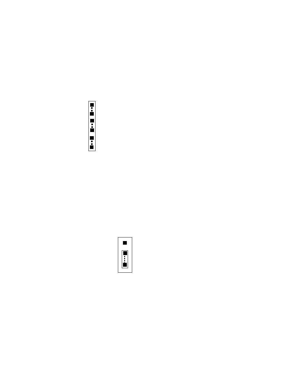
User-Counter 0 can be externally clocked by a jumper at JB2. It is adjacent to the digital connector and
connects the internal 10 MHz OSC signal to Counter 0 clock input (Figure 2-2). Using two additional
jumpers at JB2, the counters can be chained 0 to1, and 1 to 2 to yield counters of 32 or 48 bits. These
counters can also be chained externally at the 40-pin digital connector, P5.
Figure 2-2. User-Counter Clock Source and Chaining Jumpers
2.3
PACER CLOCK SOURCE SELECT JUMPER
When using the internal clock for pacing, select the desired frequency of the source supplied to the pacer
counters by setting the XTAL jumper for either 1 or 10 MHz (Figure 2-3). In most cases, 10MHz is the
appropriate choice. Use the 1MHz option only if you are using the CIO-DAS16/M1 with software
designed for the DAS16 (which would calculate pacer speed based on a 1MHz sourc to the pacer
counters).
Figure 2-3. Pacing Counter Frequency-Select Jumper
OSC
C0 (CLK 0)
O0 (OUT 0)
C1 (CLK 1)
O1 (OUT 1)
C2 (CLK 2)
The on-board 10 MHz OSC signal can be connected
directly to the clock of CTR 0 by jumping OSC to C0.
The output of CTR 0 (O0) can be chained directly to
the clock of CTR 1 (C1).
The output of CTR 1 (O1) can be chained directly to
the clock of CTR 2 (C2).
JB2
1 MHz
10
XTAL