Measurement Computing DaqBoard 3000USB Series User Manual
Page 111
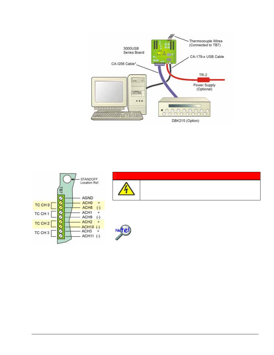
Example 2: System with a DaqBoard/3000USB Series Board
In this example a DBK215 BNC Module is connected to the 68-pin SCSI connector of a /3000USB Series
board via a CA-G56 shielded cable. However, the use of other cables is possible as noted below. Four
thermocouples are connected at the board’s TB7 Terminal Block. This means that 8 analog channels [to
obtain 4 differential TC channels] are required (see following figure). Redundant connections must be
avoided. A TR-2 power supply is being used, and is connected to the board’s external power connector.
WARNING !
Before connecting TC wires, ensure that the associated
analog channels are not in use. Failure to do so could
possibly cause equipment damage and/or personal injury.
The TB7 terminal block can be used to connect up to 4 thermocouples. The
first TC channel makes use of Analog Channel 0 for its positive (+) lead and
Analog Channel 8 for its negative (-) lead. The second TC channel uses
analog Channels 1 and 9, and so on, as indicated in the pinout to the left.
Thermocouples should only be connected in differential mode.
Appendix B includes additional information.
DaqBoard/3000USB Series devices do not have open
thermocouple detection.
Note that a CA-179-x USB cable is being used to connect the /3000USB Series board to a USB port on the
host PC.
* Any of the following 68-conductor expansion cables can be used to connect the DBK215 module option
the SCSI connector:
CA-G55
3 feet, ribbon cable.
CA-G56
3 feet, shielded expansion cable.
CA-G56-6 6 feet, shielded expansion cable.
Appendix A
886994
DBK215 A-5