Measurement Computing DaqBoard 3000USB Series User Manual
Page 78
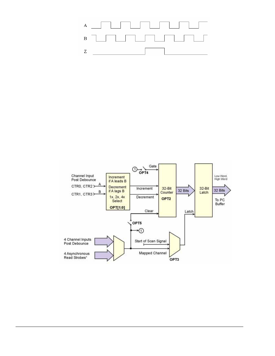
Representation of Quadrature Encoder Outputs: A, B, and Z
As the encoder rotates, the A (or B) signal is indicative of the distance the encoder has traveled. The
frequency of A (or B) indicates the velocity of rotation of the encoder. If the Z signal is used to zero a
counter (that is clocked by A) then that counter will give the number of pulses the encoder has rotated from
its reference. The Z signal is a reference marker for the encoder. It should be noted that when the encoder
is rotating clockwise (as viewed from the back), A will lead B and when the encoder is rotating counter-
clockwise, A will lag B. If the counter direction control logic is such that the counter counts upward when
A leads B and counts downward when A lags B, then the counter will give direction control as well as
distance from the reference.
An Example of Encoder Accuracy
If there are 512 pulses on A, then the encoder position is accurate to within 360 degrees/512. Even greater
accuracy can be obtained by counting not only rising edges on A but also falling edges on A, giving
position accuracy to 360 degrees/1024. The ultimate accuracy is obtained by counting rising and falling
edges on A and on B (since B also has 512 pulses.) This gives a position accuracy of 360 degrees/2048.
These 3 different modes are known as 1X, 2X, and 4X. The 3000USB Series board implements all of
these modes and functions, as described in the following options.
Encoder Mode
*There is one asynchronous read strobe for each of the four counter channels.
5-16 Counter Input Modes
887794
DaqBoard/3000USB Series User’s Manual