Ch 6 - setpoint configuration for output control, Overview, Setpoint configuration for output control 6 – Measurement Computing DaqBoard 3000USB Series User Manual
Page 83
Setpoint Configuration for Output Control
6
Overview …… 6-1
Detecting Input Values …… 6-3
Controlling Analog, Digital, and Timer Outputs …… 6-4
P2C, DAC, or Timer Update Latency …… 6-6
More Examples of Control Outputs …… 6-7
Detection on an Analog Input, DAC and P2C Updates
Detection on an Analog Input, Timer Output Updates …… 6-8
Using the Hysteresis Function …… 6-8
Using Multiple Inputs to Control One DAC Output
The Setpoint Status Register …… 6- 11
Overview
DaqBoard/3000 Series boards include a setpoint configuration feature which allows the user to individually
configure up to 16 detection setpoints associated with channels within a scan group. Each detection
setpoint can be programmed in the following ways:
o
Single Point referenced – above, below, or equal to the defined setpoint
o
Window (dual point) referenced – inside, or outside the window
o
Window (dual point) referenced, Hysterisis Mode – outside the window high forces
one output (designated “Output 2”; outside the window low forces another output,
designated as “Output 1.”
A digital detect signal is used to indicate when a signal condition is True or False, i.e., whether or not the
signal has met the defined criteria. The detect signals themselves can be part of the scan group and can be
measured as any other input channel; thus allowing real time data analysis during an acquisition.
Each setpoint can update the following, allowing for real time control based on acquisition data:
o
P2C digital output port with a data byte and mask byte
o
analog outputs (DACs)
o
timers
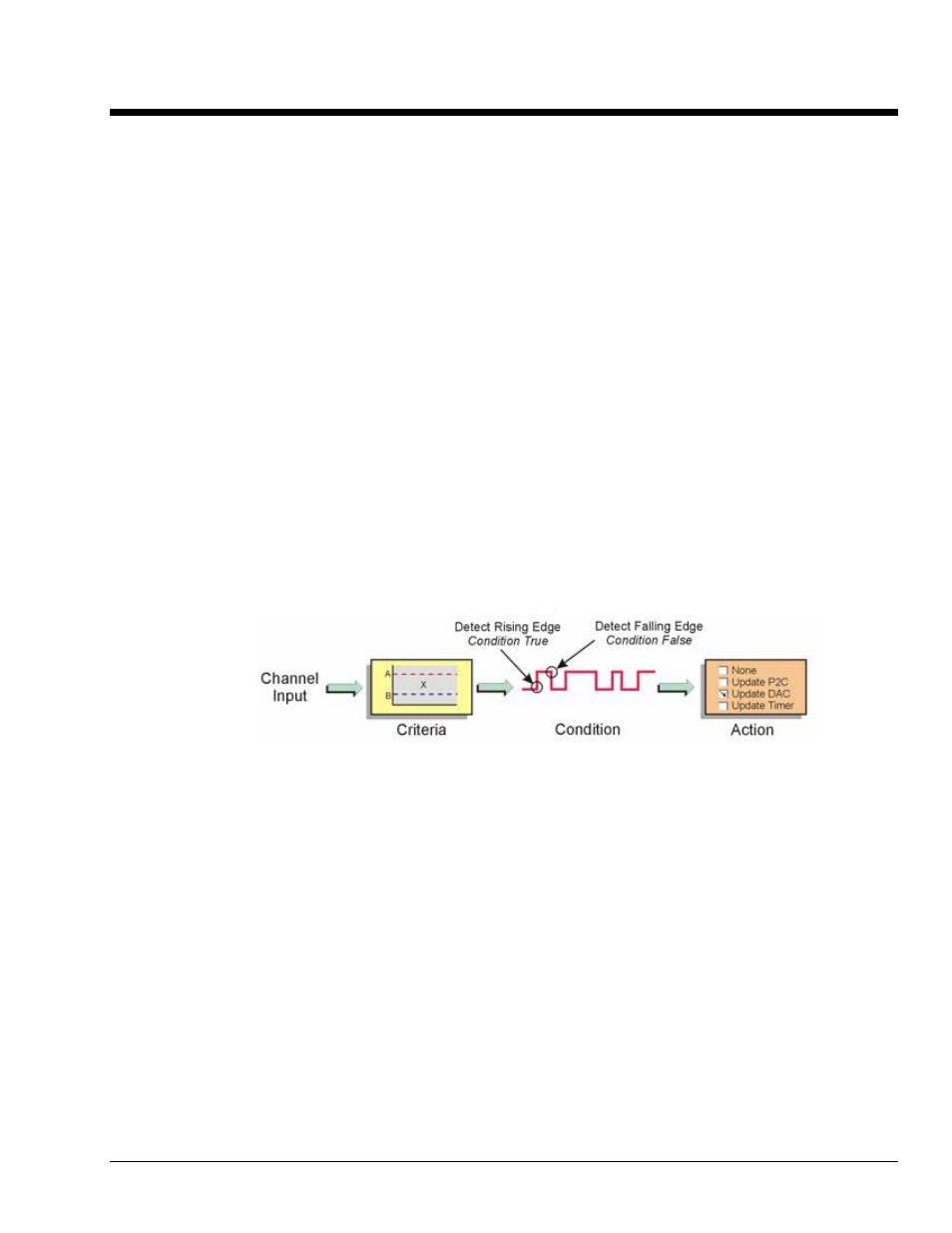
The detection module looks at the 16-bit data being returned on a given channel and generates another
signal for each channel with a setpoint applied: Detect1 for Channel 1, Detect2 for Channel 2, etc. These
signals serve as data markers for each channel’s data. It doesn’t matter whether that data is volts, counts,
period, pulsewidth, timing, or encoder position.
A channel’s detect signal will show a rising edge and will be True (1) when the channel’s data meets the
setpoint criteria. The detect signal will show a falling edge and will be False (0) when the channel’s data
does not meet the setpoint criteria. The true and false states, for each setpoint criteria, appear in the
Setpoint Status Register (see page 6-11).
DaqBoard/3000 Series User’s Manual
887794
Setpoint Configuration for Output Control 6-1