Notice, Installation – Montigo H34VO User Manual
Page 11
H-Series VO Outdoor Gas Fireplace
Page 11
XG0150 - 070714
Installation
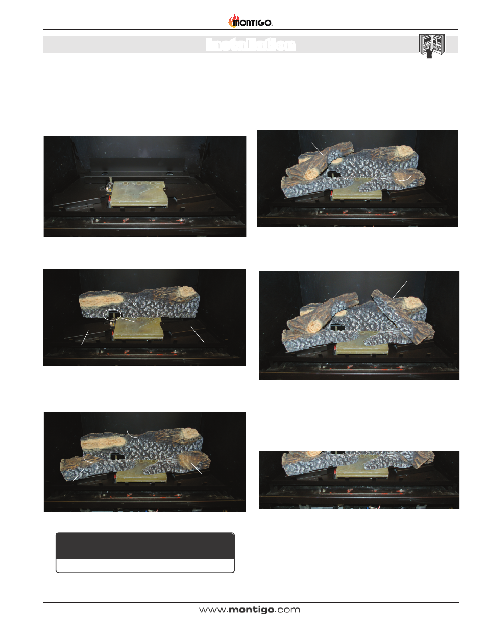
Section 8: Installing the Accessories
Top Left Log
Fireplace Base
Notch
Top Right Log
Embers
Embers
Embers
Top Right Log
Fireplace Base
Front Lef t
Base Log
Front Right
Base Log
Notch
Notch
Fireplace Base
Rear / Bottom Log
Notch in Log
Log stand
Log stand
Pilot Assembly
Fireplace Base
Air Inlets
Installing the H34VO Log Set
Installing the Logs:
The H34VO fireplace is supplied with five ceramic fibre logs. Unpack
the logs and handle them very carefully.
Step 1. Remove the glass door as described in the previous instruction.
Figure 8a. H34VO*'s Fireplace Base.
Figure 8b. Bottom/Rear log placement.
Figure 8d. Top Left log placement.
Figure 8e. Top right log placement.
Step 6. Start the fireplace. If the flame appears satisfactory, replace
the glass door. If the flame does not appear satisfactory,
double-check the air inlet and exhaust outlet pipe to ensure
that they are unobstructed.
Step 4. Place the top left log as shown in figure 8d. A flat area is
provided on the front left log, and a notch in the Rear bottom log, as
shown in figure 27c. Install the glass door. If the flame does not ap-
pear satisfactory, double-check the air inlet and exhaust outlet pipe to
ensure that they are unobstructed.
Figure 8c. Front base logs placement.
Step 2. Install Bottom Rear log as shown in Figure 8b.
Step 3. Install Both front base logs, (Figure 8c) on the log stands
provided. See Figure 8b.
Step 5. Place the top right log as shown in figure 8e. A notch is provided
on the front right log, and a impression in the Rear bottom log.
Figure 8f. Placing Embers.
Step 7. Place the Embers as shown in figure 8f. Arrange the ember
chips on top of the burner tray. Care should be taken when placing the
embers, as blocked burner ports may cause an incorrect flame pattern,
carbon deposits and delayed ignition. Also, the embers must never be
placed in a way that obstructs any of the air inlet ports, located at the
rear of the burner, as shown in figure 8a.
If logs are not placed properly, excessive sooting will result.
NOTICE