1 rotary switch and push buttons, 2 slide switches, 3 gyda mode – Nevion DWC-HD-DMUX User Manual
Page 20
DWC-HD-DMUX
Rev. F
nevion.com | 20
4.2.1 Rotary switch and push buttons
The rotary switch, labeled DLY, adjusts the phase delay from -5 to +4 video lines. It is only
functional when a sync signal, black & burst or tri-level, is present at the sync input. The
rotary switch is accessible from the board front.
The push buttons, labeled INC and DEC, are used to fine adjust the phase delay by
samples. It can adjust ±½ video line for the current video standard (or the last video
standard the board was able to lock to). Pressing a button and keeping it pressed will
accelerate the change. The LED adjacent to the button will flash for a short period of time
when the end of the adjustment range has been reached. Pressing both buttons at the
same time will return to the middle of the adjustment range, and the board will acknowledge
by flashing the INPUT and SYNC LEDs simultaneously.
4.2.2 Slide switches
The two switches at the top of the module (rear side) switch between AES out and Data
out. It DC couples the output signal when in DATA out mode, and AC couples the signal
when in AES mode.
Note that to enable Data link output on the AES connector it is also necessary
to set DIP 8 to the Off position when the board is in Manual mode (DIP 16 =
On), or when the board is in Gyda mode (DIP 16 = Off), to select Data link over
AES output in Gyda. Slide switches moved to the right routes out AES.
The switch on the left card edge switches between backplane sync input and Flashlink
distributed sync (Future feature upgrade of Flashlink frame). Switch moved up routes the
backplane sync to the card.
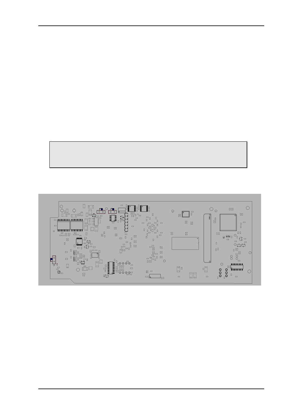
Figure 5: The figure shows a bottom view component printout of the board. Note the location
of the slide-switches.
4.3 GYDA mode
All functions of the card can be controlled through the GYDA control system. The GYDA
interface has an information page and a configuration page.
4.3.1 Information page
The information page shows a dynamic block-diagram of the board and some additional
information text. The block diagram updates with the board status, showing selected input
signal, missing signals (by red crosses over the appropriate signal lines) and signal routing
(by graphic switches). It also shows the audio matrix selections that have been made in the
configuration page.