Nevion AD6464M User Manual
Page 9
AD6464M / AD128128M
Rev. 7
nevion.com | 9
3.3.1 Module insertion
In order to insert a power supply module one must insert the module via the special plastic
guide rails into its position. Once the module is inserted, fix the module by lifting up the
handle on the front and pushing it to the upright position.
3.3.2 Module removal
In order to remove a power supply module, one must pull down the handle on the front
downwards to a horizontal position, and pull the module out with the bar on top of the power
module.
3.3.3 How to connect power to the Modular AES/EBU Digital Audio Router
There are two power connectors on the back of the frame. These connectors are for AC
mains connection.
Use an IEC 320 connector to connect AC mains to the Modular AES/EBU Digital Audio
Router frame.
There is a switch on the right hand side of the power supply module that selects
mains voltage. The mains voltage can be either 110VAC or 230VAC. This switch
must be set in the correct position, depending on the mains voltage on the
router’s site.
Failing to select correct AC mains voltage properly may damage the Power
Supply Unit.
If the frame is equipped with a single power supply module, only one AC mains connection is
used. However, if the frame is equipped with dual, redundant power supply modules, both
AC mains connectors must be used, preferably from two different mains circuits.
3.3.4 Status LEDs and Relay contacts
There are 2 LEDs on the front of each power supply module, and they indicate the following:
The upper, RED LED should be normally OFF. If it is ON, there is a power supply
failure, indicating that the power supply module must be replaced.
The lower, GREEN LED must be ON when mains power is connected. If this LED is
OFF, it means that there is no mains power supplying the frame.
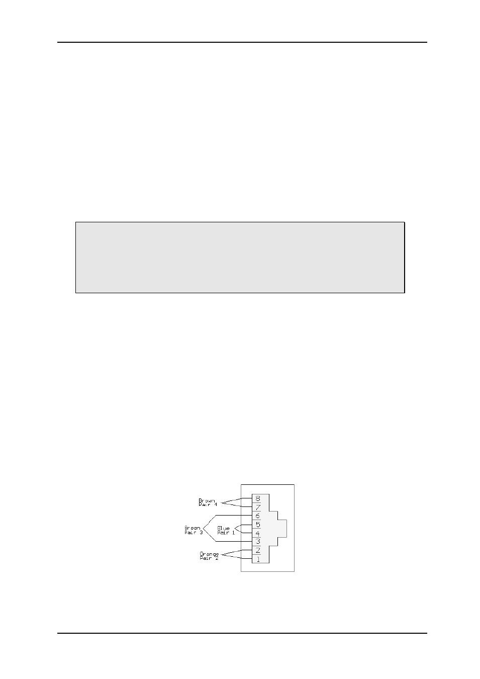
There are also two Power fail alarm relay contacts on the rear side of the frame; see Chapter
1 for details. Each installed PSU module has a separate pair of contacts. The relay contact is
normally open, and the contact closes on power failure.
The PSU module A alarm is formed by contact between Pin 3 and Pin 6 (Green pair)
The PSU module B alarm is formed by contact between Pin 1 and Pin 2 (Orange pair)