Nortec HP Series User Manual
Page 21
HP Series Installation Manual | 18
Installation of the Piping Between Valve Block and Manifolds
The valve block should be located in such a way as to feed the manifolds using the supplied
piping and fittings. Refer to the piping diagram for your specific unit (On/Off, 3 Stage, 6 Stage).
For High-Resolution HP HVAC installations, refer to the piping diagram included in the
documentation package from proper piping.
It is helpful to place the valve block in its approximate location to assist with measuring piping
lengths and placing fittings. The valve block can be installed in the duct or outside of the duct.
The piping between the valve block and the manifolds should have a slight decline towards the
valve blocks. This allows for water to drain from the manifolds and lines when the system is not
in use.
In installations where water hammer is of concern, it is recommended to install some flexible
piping between the valve block and the manifold feed lines. Using flexible feed lines between
the valve block and the manifold supply piping can also simplify the installation procedure and
allow for some misalignment among the manifold feed lines and the valve block. The valves are
threaded to accept ½” G fittings.
A qualified plumber should install all pipe-fittings and perform connections.
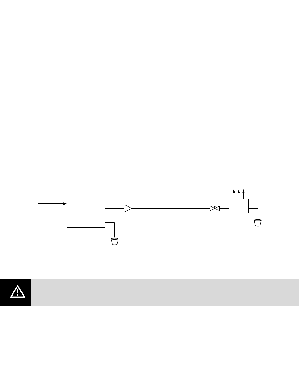
Pump Skid
Valve
Block
RO or DI Water
25
– 60 psig
Funnel drain
with air gap
Check valve
(2546701)
½” OD SS Tube
Needle Valve
(2527660)
To Manifolds In Duct
(3/8" OD SS Tube)
Figure 13: Hydraulic Schematic for HP Systems
It is strongly recommended to flush all lines with clean with clean water prior to installation.
This prevents any accumulated dirt, loose flash, or metal fillings from degrading nozzle
performance.